D-serie LEVEL II.pdf - 第112页
Axis Dynamics Position Measuring System Track Signals and Zero Pulse Signal S tuden t Guide Advanced Level 2 SIPLACE D Series Axis Dynamics EN 05/2007 7-6 7.2 Position Measuring System 7.2.1 T rack Signals and Zero Pulse…
Axis Dynamics
Axis Dynamic Basics
Student Guide Advanced Level 2 SIPLACE D Series
EN 05/2007 Axis Dynamics
7-5
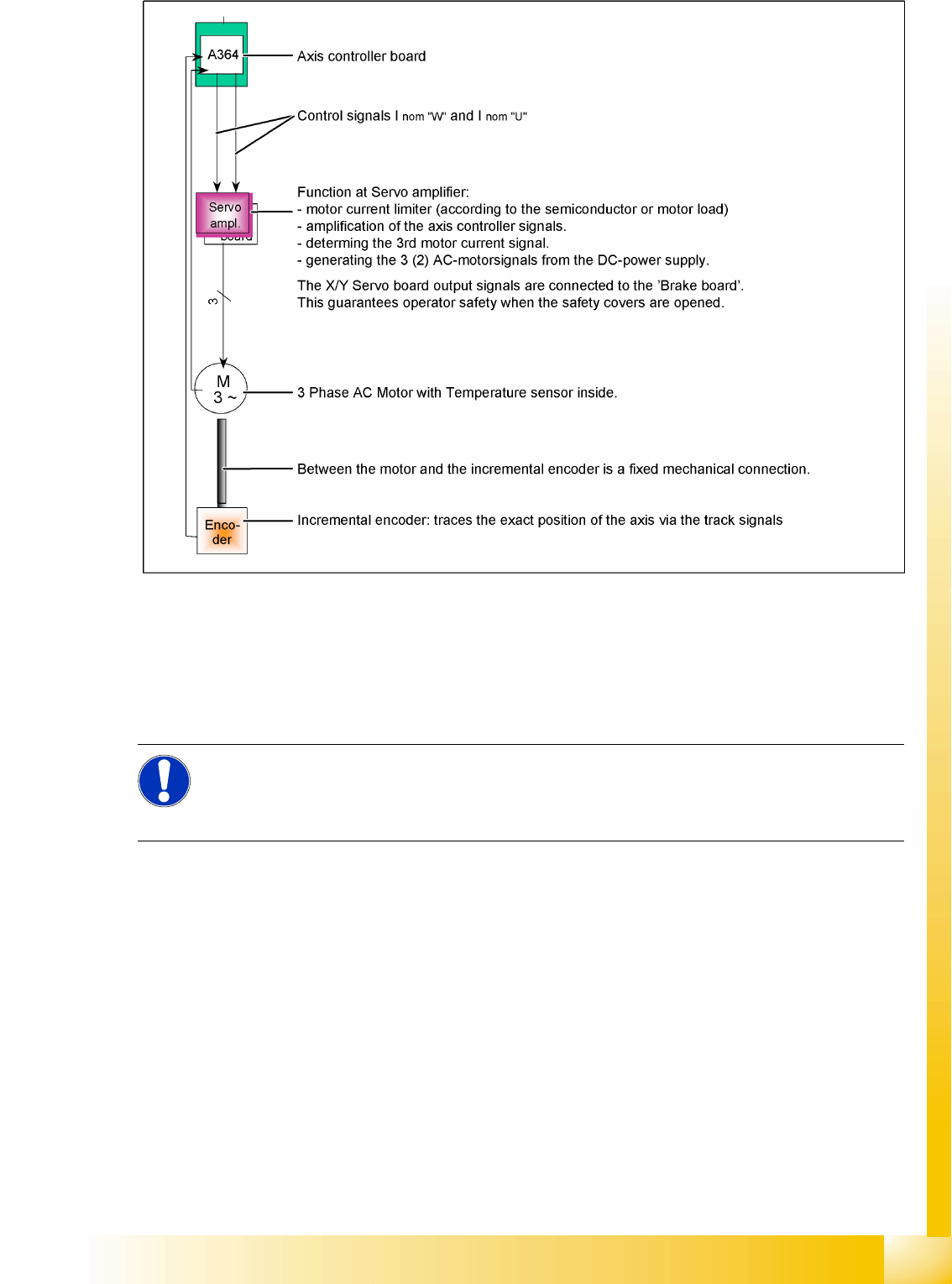
7-3: Axis block diagram example X or Y-axis of HF/Siplace X machine
Although the various axis types differ in details, all control tasks are handled by the axis controller. Two
control signals for 2 or 3 phase axis drive are transmitted to the servo. For DC drives, we use the same
hardware principle, with only one control signal to the servo amplifier. The only feedback is provided by
the track signals from the incremental encoder to the axis controller - a tacho (Z/DP axis) is not
connected to the axis system.
See also:
J 7.1 Axis Dynamic Basics [J7-1]
NOTE:
In the case of mechanical or electrical faults, the quality of the A364 axis controller is such that
the error state from longer positioning times or signal changes will only be visible if the deviation
is very significant.
Axis Dynamics
Position Measuring System Track Signals and Zero Pulse Signal
Student Guide Advanced Level 2 SIPLACE D Series
Axis Dynamics EN 05/2007
7-6
7.2 Position Measuring System
7.2.1 Track Signals and Zero Pulse Signal
Our Axes systems consists of the following parts.
Axis controller for main board
Servo amplifier
Motor
Position measuring system with incremental scale and encoder
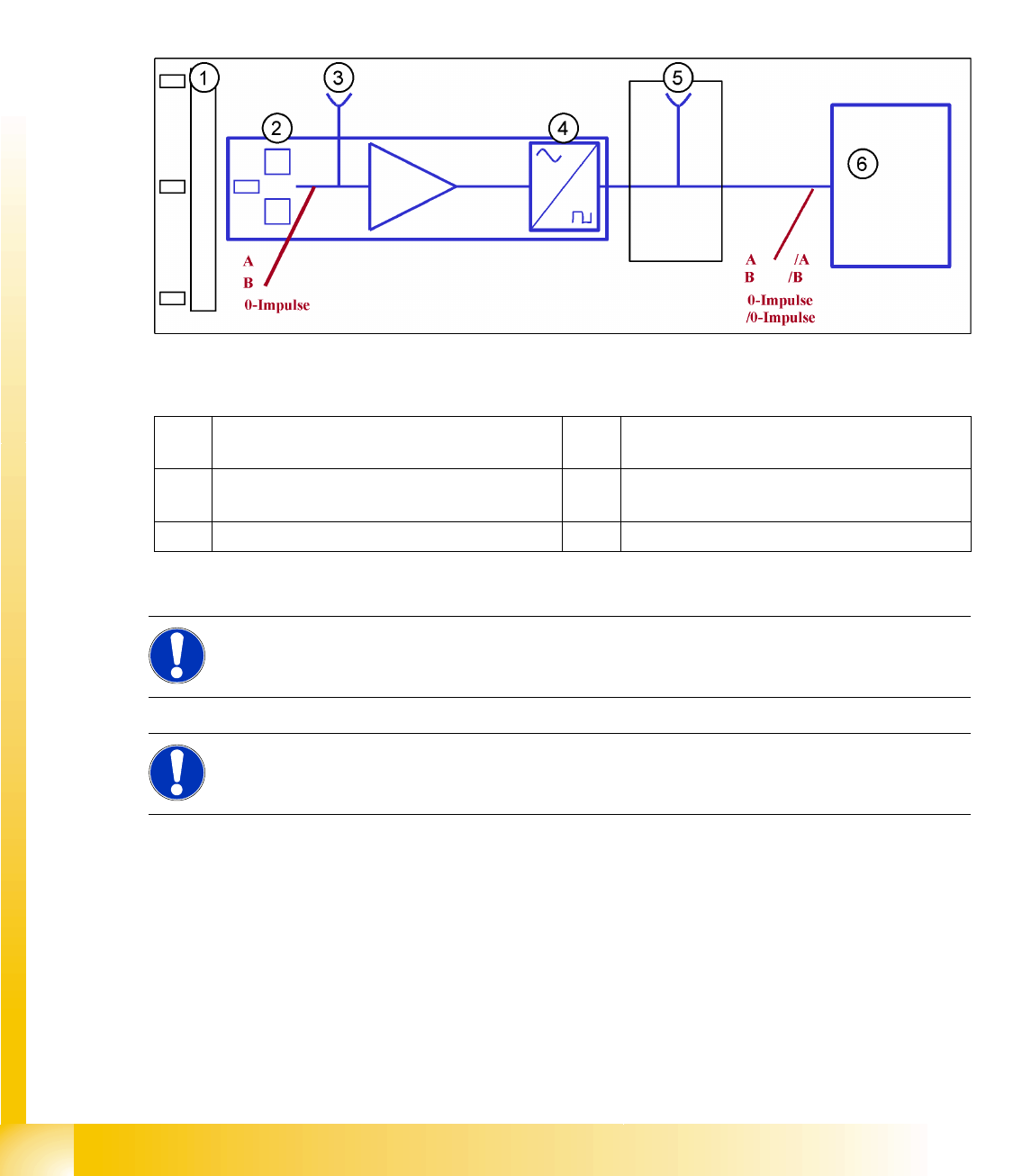
7-4: Principle circuit for position measuring systems
Legend
The axis control system with closed position control loop determines the axis position directly, based
on the mechanical movement of the axis. The position measurement system generates analog track and
zero pulse signals during movement over the incremental scale. An amplifier, a multiplier switch and a
signal former are integrated into the encoder housing. A test connector for digital signals is either
installed on the next interface board or the digital signals are measured at track A/B and the zero pulse
output of the SIPLACE axis tester. The track signals are the only feedback loops in all the axis control
systems of the SIPLACE machine. This means that each track recognition error affects the axis control
system. The gantry axes immediately stop at a fault; the head axes finish the positioning to target before
showing a track signal error.
1 Incremental scale with zero pulses 4 Electronic signal multiplication and signal
digitalization
2 Incremental encoder for track A/B and zero
pulse signals (O pulse.)
5 Test output digital signals
3 Analog signal output and amplifier 6 Axis controller
NOTE:
The incremental encoders in 1 field lens technology have the same general construction. The
transmitter and receiver of A/B count signals are located behind a common lens window.
NOTE:
This new incremental encoder supplies track signal output amplitudes of between 1.8 and
3.6 Vss, compared to the old incremental encoder which achieved a maximum value of 2.5 Vss.
Axis Dynamics
Track Signals and Zero Pulse Signal Position Measuring System
Student Guide Advanced Level 2 SIPLACE D Series
EN 05/2007 Axis Dynamics
7-7
The position is determined by a position counter on the axis controller. The moving direction of the axis
is determined by the phase shift of the track signals An advanced track A signal indicates movement to
the right, while an advanced track B signal indicates movement to the left. To make the encoder system
robust for the high resolution we multiply the frequency of the analog signal and create a high resolution
digital measuring system.
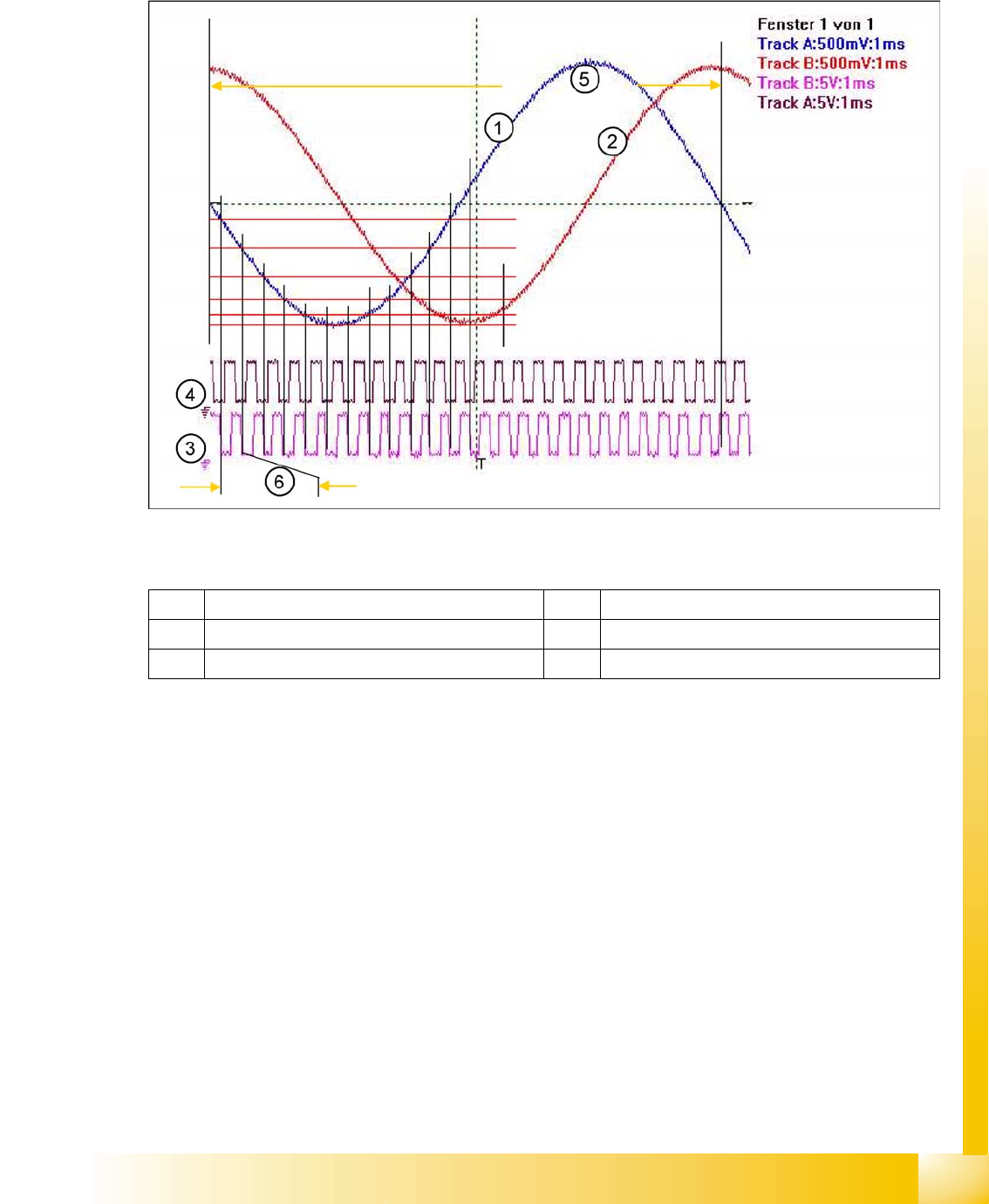
7-5: Principle signal multiplication at analog Track signals of a gantry axis
Legend
The signal multiplication can be realized as a Schmitt trigger action. During comparison of the analog
and digital axis signals, a signal multiplication of 25 (see diagram above), 10 or just 1 can be recognized.
The track signals of the C&P head axes can only be measured as digital signals i.e. The analog signals
are directly converted in the encoder housing, without provision of a test connection for the analog
signals.
1 Analog track A signal incremental encoder 4 Digital track B signal at Test connector
2 Analog track B signal Incremental encoder 5 Period time of analog track signal
3 Digital track A signal at Test connector 6 Period time of digital track signal