D-serie LEVEL II.pdf - 第117页
Axis Dynamics Servo Amplifier TBS .. and SDS ... Axis Control Assemblies S tude nt Guide Advanced Level 2 SIPLACE D Series EN 05/2007 Axis Dynamics 7-1 1 7.3.2 Servo Amplifier TBS .. and SDS ... 7-9: Servo amplifier Serv…
Axis Dynamics
Axis Control Assemblies Axis Controller
Student Guide Advanced Level 2 SIPLACE D Series
Axis Dynamics EN 05/2007
7-10
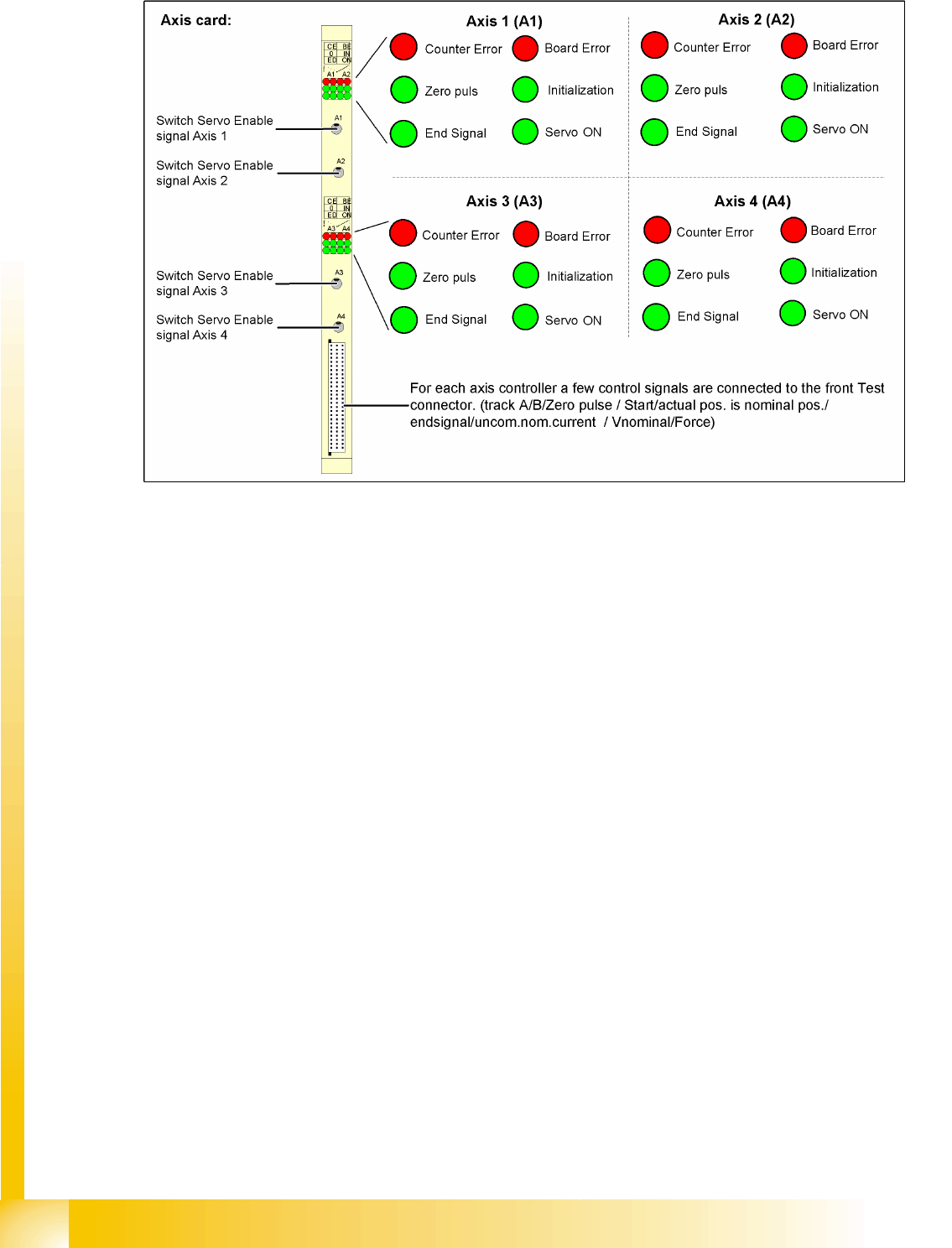
7.3.1 Axis Controller
7-8: View of the SIPLACE machine axis controller A364 and its test signals
The axis controller receives the target position and the start signal from the MC. All relevant calculations
and control actions are performed by the axis controller.
The axis controller A364 in the SIPLACE machine is socket coded. This means that no address switches
need to be set when parts are replaced.
The communication and axis control functions are handled by the axis controller.
The relevant
BIOS SW is responsible
Application 1, Application 2
Due to the various types of drives (motors), you will need different entries for the control parameters.
This results in different firmware versions for the axis types.
Axis Dynamics
Servo Amplifier TBS .. and SDS ... Axis Control Assemblies
Student Guide Advanced Level 2 SIPLACE D Series
EN 05/2007 Axis Dynamics
7-11
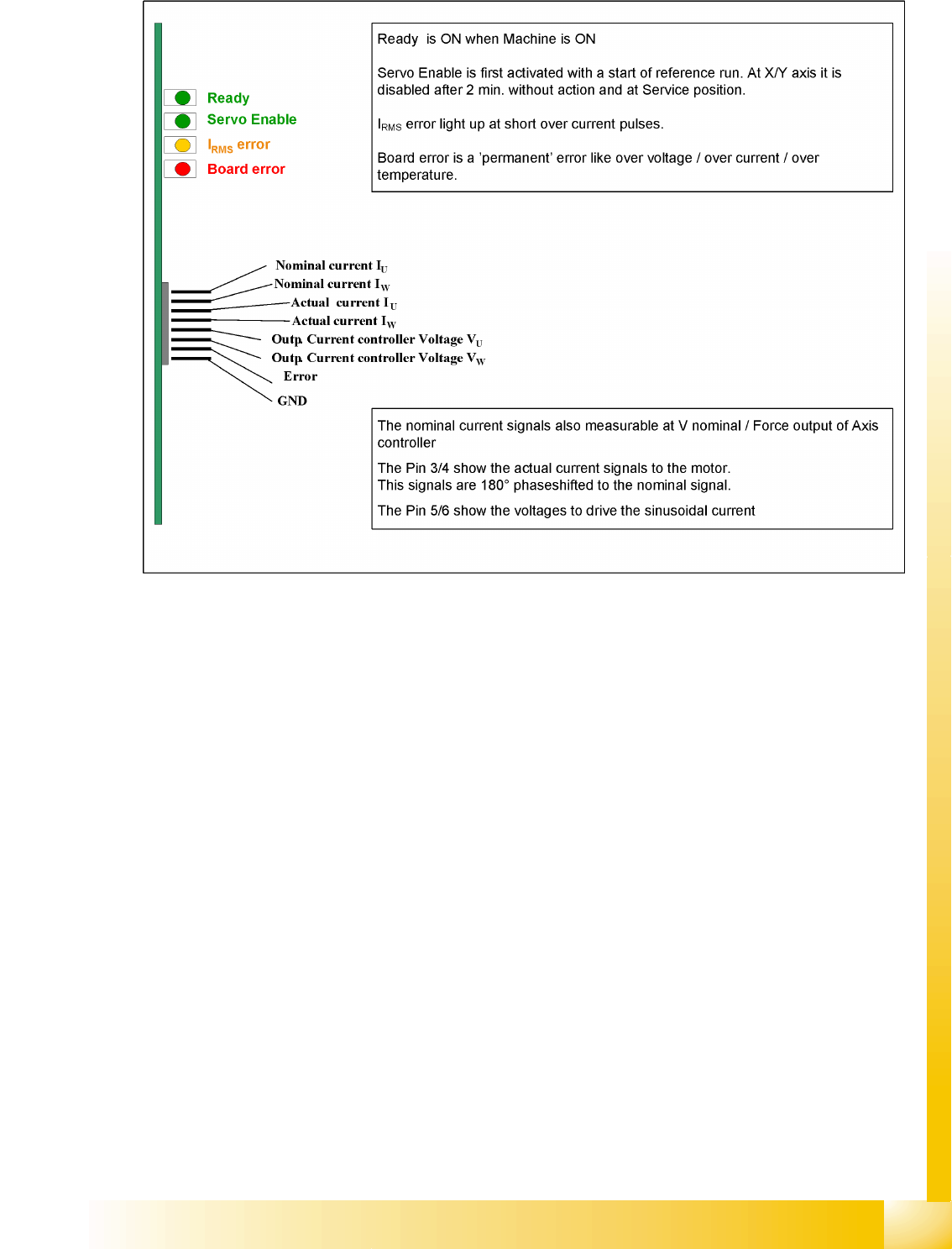
7.3.2 Servo Amplifier TBS .. and SDS ...
7-9: Servo amplifier
Servo amplifiers of type TBS are used for the X/Y and star axes, while SDS servo amplifiers are used
for the Z and DP axes. Depending on the individual input, SDS servo amplifiers can process voltages of
up to 60 VDC or 120 VDC.
This SDS and TBS Servo amplifiers are to reset by Servo disable / Servo enable at Axis controller board.
All servos are individually set for the maximum motor current of the drive unit connected. This means the
servo amplifiers have to be mounted specifically for the current axis type.
Measurement pin MP7:
In case of an error on the Servo amplifier, it is possible to measure on the analog output pin MP7 different
voltages to determined the error.
Overvoltage -1 V
Overcurrent -2 V
Overtemperature -3 V
Nominal current exceeded -4 V

Axis Dynamics
Gantry Axis Control Track Signals and Zero Pulse
Student Guide Advanced Level 2 SIPLACE D Series
Axis Dynamics EN 05/2007
7-12
7.4 Gantry Axis Control
7.4.1 Track Signals and Zero Pulse
Track signals and zero pulse signals should be produced reliably by correct mechanical installation.
Should errors or malfunctions occur, check the machine as usual.
Previous incremental encoders show track A/B count signal amplitudes of 1.8 to 2.5 Vss.
New incremental encoders with 1 field optical systems have count signal amplitudes of 1.8 to 3.6 Vss.
7.4.2 Checking the X-Axis Dynamics
7.4.2.1 Overview
The inspection of dynamics occurs with the following signals:
Deviation of position
Uncommutated target current value
End signal ( Adapter board Axis in target position)
Actual position = target position signal (trigger for position deviation)
NOTE:
For further details, refer to the service manual for the respective machine.
NOTE:
For detailed information about checking the dynamics, refer to the settings instructions.
Before adjusting the axes, ensure that the machine has reached its operating temperature.
Switch the machine on at least 30 minutes before you begin work.