D-serie LEVEL II.pdf - 第122页
Axis Dynamics Gantry Axis Control Checking the Y-Axis Dynamics S tuden t Guide Advanced Level 2 SIPLACE D Series Axis Dynamics EN 05/2007 7-16 7.4.3.3 Y -Axis T ravel Time T able (D3) In software version 603 the gantry t…
Axis Dynamics
Checking the Y-Axis Dynamics Gantry Axis Control
Student Guide Advanced Level 2 SIPLACE D Series
EN 05/2007 Axis Dynamics
7-15
7.4.3 Checking the Y-Axis Dynamics
7.4.3.1 Measurement Setup
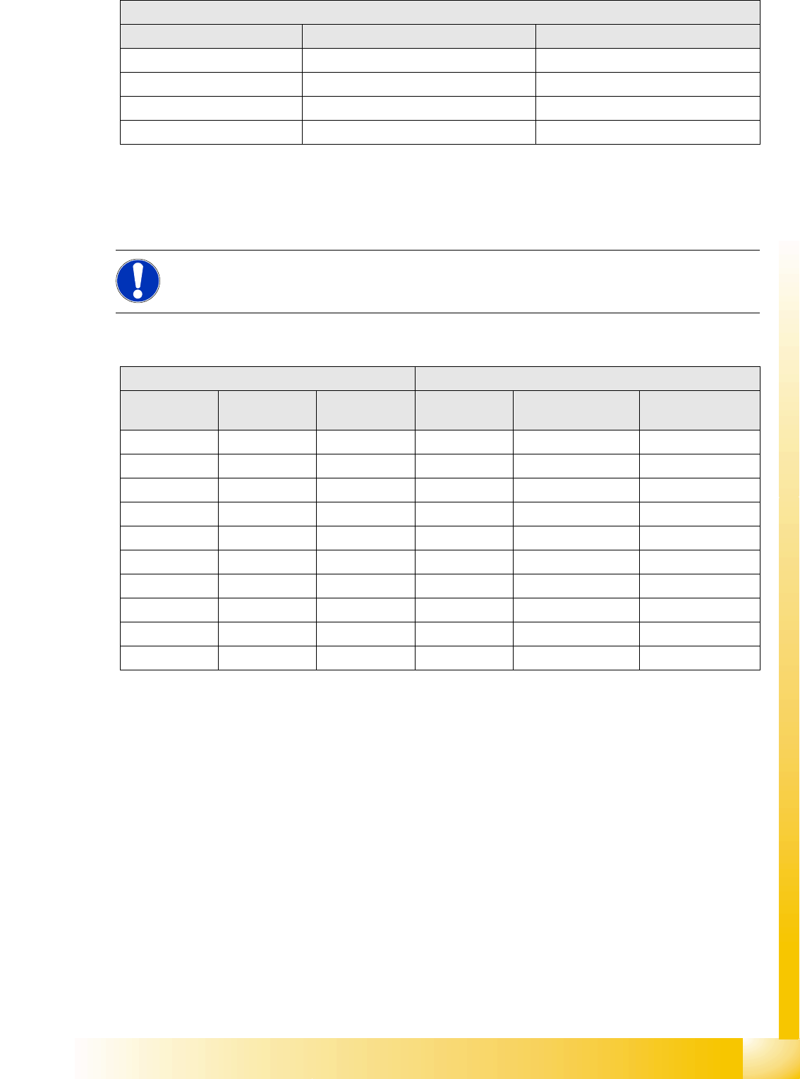
7.4.3.2 Y-Axis Travel Time Table (D1/D2)
50000 87 +/-10
100000 114 +/-10
200000 162 +/-10
300000 205 +/-15
X-axis gantry axis with DLM2 (C&P12)
Range / digit Target time / ms Tolerance /ms
NOTE:
The measurement procedure is prepared and performed identically to that for the X-axis
D2: C&P6 or C&P12 D1: C&P6 or C&P12 and P&P
Range / digit Target time /
ms
Tolerance /ms Range / digit Target time / ms Tolerance /ms
500 45 +/-5 500 45 +/-5
1000 50 +/-5 1000 50 +/-5
2000 59 +/-5 2000 62 +/-5
5000 66 +/-5 5000 75 +/-5
15000 79 +/-10 15000 91 +/-10
20000 90 +/-10 20000 105 +/-10
50000 118 +/-10 50000 133 +/-10
100000 150 +/-10 100000 172 +/-10
200000 196 +/-15 200000 228 +/-15
600000 378 +/-15 600000 425 +/-15
Axis Dynamics
Gantry Axis Control Checking the Y-Axis Dynamics
Student Guide Advanced Level 2 SIPLACE D Series
Axis Dynamics EN 05/2007
7-16
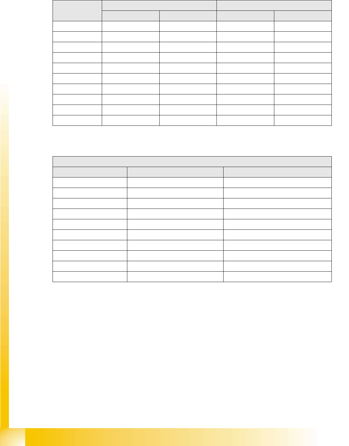
7.4.3.3 Y-Axis Travel Time Table (D3)
In software version 603 the gantry travel times for the C&P head are about 5 ms faster than before:
7.4.3.4 Y-Axis Travel Time Table (D4)
Range / digit Y gantry axis (C&P6, C&P12) Y gantry axis with Twin head
Target time / ms Tolerance /ms Target time / ms Tolerance /ms
50033+/-535+/-5
100034+/-540+/-5
200037+/-546+/-5
500044+/-553+/-5
15000 61 +/-5 68 +/-5
20000 68 +/-5 76 +/-5
50000 96 +/-10 108 +/-10
100000 139 +/-10 147 +/-10
200000 190 +/-10 199 +/-10
600000 347 +/-15 357 +/-15
Travel times with 603 for Y gantry axes, with the various different head configurations
D4: Y gantry axis with DLM3 (DLM2) (C&P12)
Range / digit Target time / ms Tolerance /ms
500 41 +/-5
1000 43 +/-5
2000 45 +/-5
5000 55 +/-5
15000 70 +/-5
20000 75 +/-5
50000 108 +/-10
100000 143 +/-10
200000 188 +/-10
600000 370 +/-15
Axis Dynamics
Positioning Time for C&P6 Head Axis Control C&P6/12
Student Guide Advanced Level 2 SIPLACE D Series
EN 05/2007 Axis Dynamics
7-17
7.5 Axis Control C&P6/12
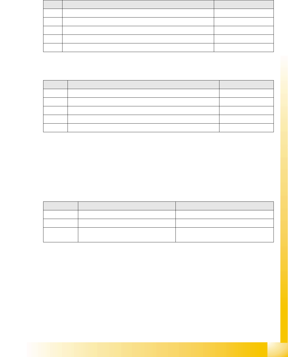
7.5.1 Positioning Time for C&P6 Head
7.5.2 Positioning Time for C&P12 Head
7.5.3 Track Signals for Head Axes
The track signals have been given a significant role in the new drive concept of SIPLACE machines.
They are responsible for the accurate positioning of the axes and are used as the only feedback signal
for the closed control circuit, so that the track signals have a key influence on the dynamic behavior of
the axes.
7.5.3.1 Overview
Axis Mode/path Positioning time
Star Axis continuous run / 1 Star step 70 ms +/-3 ms
Z Absolute, free space / 685 digits 30 +/-3 ms
Z Light barrier, into calibration tool pocket / approx. 685 digits 30 +/-3 ms
DP 200 digits 38 ms +/-3 ms
DP 7200 digits 85 ms +/-3 ms
Axis Mode/path Positioning time
Star Axis continuous run / 1 Star step 43ms +/-3ms
Z Absolute, free space / 685 digits 21ms, -1ms
Z Light barrier, into calibration tool pocket / approx. 685 digits 21 +/-3ms
DP 100 digits 13ms +/-3ms
DP 3600 digits 39ms +/-3ms
Axes Mechanical settings Oscilloscope diagram
Star 25x: Resolution 1/1000° Digital track signal amplitude 3.6Vpp
Z nothing Digital track signal amplitude 3.6Vpp
DP DP read head set to 1.5 mm, parallel to the
glass
Digital track signal amplitude 3.6Vpp
Oscilloscope settings