D-serie LEVEL II.pdf - 第143页
C&P6/12 Placement Head Vacuum Check for Pickup/Place Circuit Vacuum Check S tude nt Guide Advanced Level 2 SIPLACE D Series EN 05/2007 C&P6/12 Placement Head 8-17 Benefits of Special Mode "Sl ow Start" …
C&P6/12 Placement Head
Travel Profiles - Placement Z-Axis Up
Student Guide Advanced Level 2 SIPLACE D Series
C&P6/12 Placement Head EN 05/2007
8-16
8.4.2 Z-Axis Up
8.4.2.1 Standard Mode - Placement: Z-Axis Up
8.4.2.2 Placement: Z-Axis Upwards with "Slow Start"
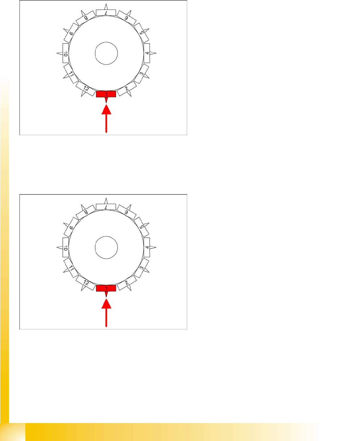
8-13: Detailed component placement procedure: Z-axis up
LB down switches:
End position signal for downwards and valve
positioning drive "ON" for air blast
Measurement of air blast pressure during
placement
Start signal for upwards movement
Z-axis starts:
Positioning of Z-axis upwards
LB up switches:
Electromagnetic valve for air blast OFF
Reset LB down signal
Start signal for gantry axes
Z-axis end position signal (Z-axis at 0 position):
Enables vacuum query: "Segment airtight"
after placement (SR/MC503)
Start signal for star axis
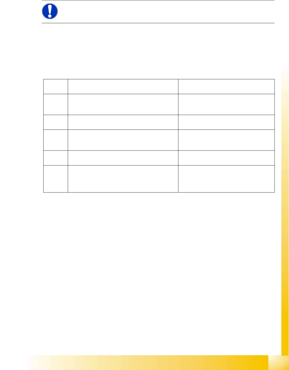
8-14: Detailed component placement procedure: Z-axis upwards with slow
start from placed component
From LRU/LRL 503 and SIPLACE Pro, this
placement type can "only" be programmed in the
CS "for SR/MC 503 stations and higher".
LB down switches:
End position signal for downwards and valve
positioning drive ON for air blast
Measurement of air blast pressure during
placement
Start signal for upwards movement
Z-axis starts:
Positioning Z-axis up with reduced starting
speed for the first 44 digits
LB up switches:
Electromagnetic valve for air blast OFF
Reset LB down signal
Start signal for gantry axes
Z-axis end position signal (Z-axis at 0 position):
Enables vacuum query: "segment airtight?"
after placement (SR/MC503)
Start signal for star axis
C&P6/12 Placement Head
Vacuum Check for Pickup/Place Circuit Vacuum Check
Student Guide Advanced Level 2 SIPLACE D Series
EN 05/2007 C&P6/12 Placement Head
8-17
Benefits of Special Mode "Slow Start"
The component stays on the board even if the soldering paste has a low holding force.
8.5 Vacuum Check
8.5.1 Vacuum Check for Pickup/Place Circuit
Machine functions and component presence are checked in regular function tests during the pickup and
place processes. These relate to the vacuum values during the reference run as comparative values.
8.5.2 Vacuum Check for Holding Circuit
In order to detect any leaks in the segments which are not in the pickup/place position, a vacuum check
for the holding circuit is performed after placement.
The vacuum check for the holding circuit is only performed under the following conditions:
The placement sequence has been completed. (All components have been placed.)
There were no vacuum or Vision errors during the placement process.
The vacuum value must exceed a threshold of 750 mbar. This threshold also depends on the height of
the machine when installed.
NOTE:
However, this option makes the placement procedure around 20 ms longer than the standard
placement procedure.
1. Vacuum check before pickup
Vacuum check with Z-axis still in zero position
"Vacuum closed" value:
To valve check
For 604
only (new)
Vacuum check after start down
Only at pickup for components with function "early
vacuum"
"Vacuum open" value:
Check whether segment is empty
2. Vacuum check after pickup
Vacuum value for Z-axis at light barrier up position
First component presence check:
Starts gantry positioning
3. Vacuum check after pickup
Vacuum value for Z-axis at zero position
Second component presence check:
Check whether component is processed
further in star positions.
4. Vacuum check before placement
Vacuum value with Z-axis still in zero position
Presence check before placement
5. Vacuum check after placement
Vacuum check when Z-axis is again in zero position
"Vacuum closed" value:
To valve check
This is the reference value for vacuum check
before pickup.

C&P6/12 Placement Head
Vacuum Check Throughput Test for Vacuum-Holding Circuit
Student Guide Advanced Level 2 SIPLACE D Series
C&P6/12 Placement Head EN 05/2007
8-18
8.5.3 Throughput Test for Vacuum-Holding Circuit
Through the installation of the placement head, the silicon tube for supplying the holding circuit with
vacuum can become jammed, especially in HF/X/D3 machines.
The lower throughput reduces the holding force for the components during the placement process. This
means that components can be displaced on the nozzle, both before and after the component camera.
If this happens before the camera, the component may be moved out of the pickup tolerance. After the
camera, displacement can lead to random, uncorrectable placement offsets.
This fault can be recognized with the SITEST 'throughput test".
C&P12/6
Perform the following steps:
X Return all C&P head nozzles.
X Measure the holding circuit vacuum. Typical values are around 900 mbar (values over 900 are
shown as 900).
X Open a segment in the reject circuit and
X step the star one position.
X Measure the holding circuit vacuum. Values higher than 800 mbar are OK.
X Open another segment in the reject circuit and
X step the star one position.
X Measure the holding circuit vacuum. Values higher than 700 mbar are OK.
Values around 600 mbar are reached at around half the diameter of the silicon supply tube.
Vacuum values in the holding circuit which only reach 500 mbar are no longer sufficient to guarantee the
holding circuit function. (Values under 400 mbar are only shown as -1)