D-serie LEVEL II.pdf - 第148页
C&P6/12 Placement Head Settings Determining the Zero Point Correction for the C&P Head Star Axis S tuden t Guide Advanced Level 2 SIPLACE D Series C&P6/12 Placement Head EN 05/2007 8-22 8.6.4 Determining the …
C&P6/12 Placement Head
Settings for C&P Head - Details Settings
Student Guide Advanced Level 2 SIPLACE D Series
EN 05/2007 C&P6/12 Placement Head
8-21
8.6.3 Settings for C&P Head - Details
The zero point correction for the star axis is so significant that it will be described separately below.
Mechanical adjustments air blast
tubes on the star
Check with your eyes Check the distance between
incremental encoder DP and air blast
tubes.
Adjustments tube for air blast supply feeler gauge Air blast tubes should be approx. 0,7
mm over the frame of the circular
guide
Adjustments air pressure values Compressed air testing device 150 mbar on open 9x4 nozzle
reject circuit (not used for reject at
HF and X machine)
250 mbar (200 - 300 mbar) The reject circuit does not have a
sensor
Description Tools &Equipment Adjustments
NOTE:
For a detailed description of the C&P6/12 head settings, refer to the D-series service manuals,
in chapter
Settings --> C&P heads
.
C&P6/12 Placement Head
Settings Determining the Zero Point Correction for the C&P Head Star Axis
Student Guide Advanced Level 2 SIPLACE D Series
C&P6/12 Placement Head EN 05/2007
8-22
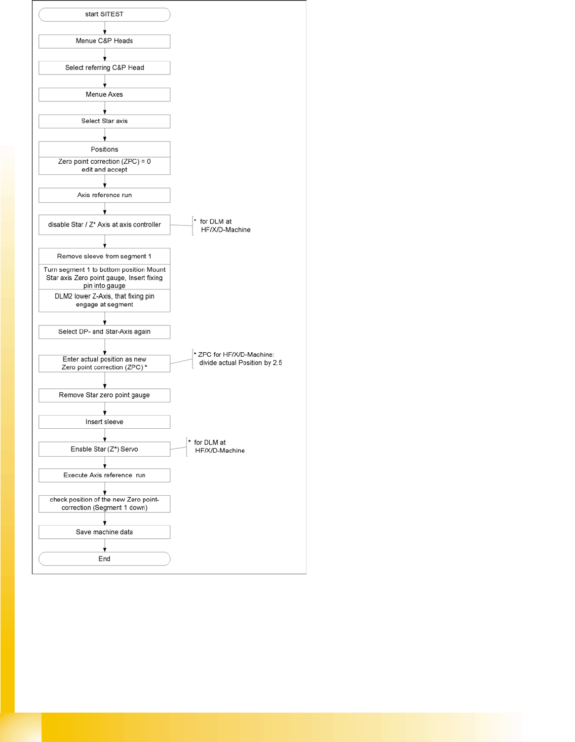
8.6.4 Determining the Zero Point Correction for the C&P Head Star Axis
8-15: Flow diagram for zero point correction
During this process, make sure you adhere to the
procedure exactly and observe the comments
about the individual steps.

C&P6/12 Placement Head
Determining the Zero Point Correction for the C&P Head Star Axis Room for Your Sketches and Notes
Student Guide Advanced Level 2 SIPLACE D Series
EN 05/2007 C&P6/12 Placement Head
8-23
8.7 Room for Your Sketches and Notes