D-serie LEVEL II.pdf - 第153页
Component Handling Changeover Table Construction Overview S tude nt Guide Advanced Level 2 SIPLACE D Series EN 05/2007 Component Handl ing 9-3 9.1.2 Changeover T able Construction The S feeder changeover tables on the 4 …
Component Handling
Overview Technical Data - Changeover Tables
Student Guide Advanced Level 2 SIPLACE D Series
Component Handling EN 05/2007
9-2
9.1.1 Technical Data - Changeover Tables
Feeder capacity for D1/
D2 machines:
90 tracks for 8 mm tapes with 3x8 mm feeders
60 tracks for 8 mm tapes with 2x8 mm feeders
Feeder capacity for D4
machines:
144 tracks for 8 mm tapes with 3x8 mm S feeders
96 tracks for 8 mm tapes with 2x8 mm S feeders
Locations for D1/D2
machines:
2 changeover tables with integrated waste tape container
15 feeder positions, each one with 30 mm on each changeover table
Option: Waffle Pack Changer (10 feeder positions – 30 mm wide)
Locations for D4
machines:
4 changeover tables with integrated waste tape container
12 feeder positions, each one with 30 mm on each changeover table
Feeders: Tapes, bulkcase, linear feeder, Siplace S feeder (F4, F5,S20, S23, S25HM,
S27HM, HS50, HS50+,HS60), OEM feeder, surftape feeder (8, 12, 16, 24
mm), manual trays
Interface to the
machine
Plug-in connection to machine
- Power supply
- CAN bus connection
- Closing the safety loop
- Compressed air connection
- Splice point recognition connection (optional)
Changeover table
height
depend from the machine height:
830 mm ± 15 mm (standard)
900 mm ± 15 mm (SMEMA)
930 mm ± 15 mm (SMEMA)
950 mm ± 15 mm (SMEMA)
Component Handling
Changeover Table Construction Overview
Student Guide Advanced Level 2 SIPLACE D Series
EN 05/2007 Component Handling
9-3
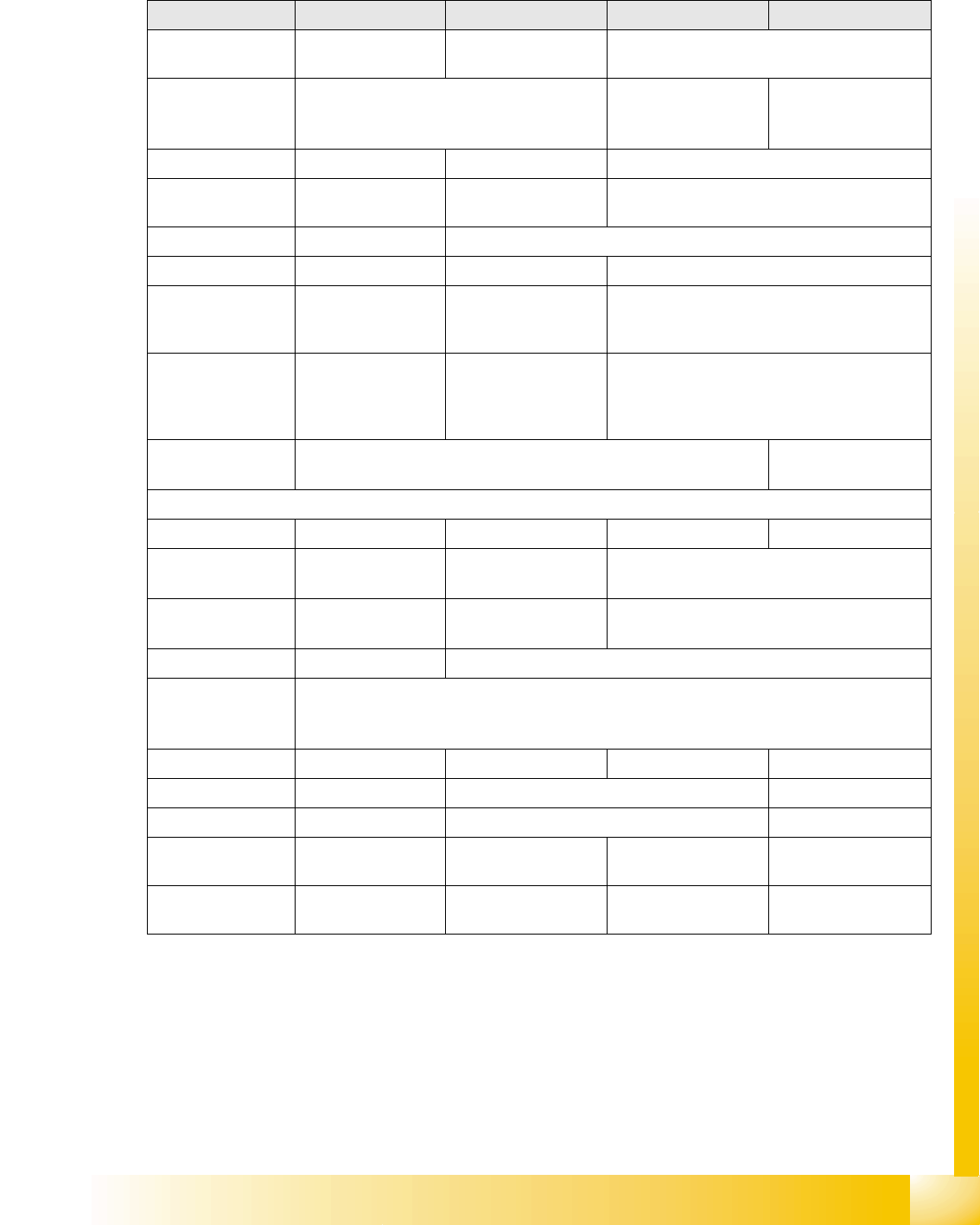
9.1.2 Changeover Table Construction
The S feeder changeover tables on the 4 machine types in the D-series have the following common/
different features:
Assembly D4 D3 D2 D1
Feeder table plate HS x0 compatible
(440 mm)
X machine with S
table, compatible
Widened table, new (562 mm)
Changeover table
position in the
machine
1 Location 1 D2 pos. Location 1 D1 pos.
Magnetic strip Glued and screwed Glued and screwed
Connection type Harting plug on
flexible connection
ODU connector, fixed
- as central front plug.
Harting plug on flexible connection
Different coding to D4
Feeder location 12 15
CAN Bus 500kbit/s 1 Mbit/s 1Mbit/s
Fitting the
changeover table
See D2/1 Table automatically
connected by table
docking unit
Move in table; connect table; lower table and
close feeder cover flap
Pneumatic switch See D2/1 ---- In the machine, always in lowered position
and track 1 always with feeder / safety cover
(if fitted) ensures safe table position; safety
cover is always on table plate.
Table plate for WPC
option
--- Yes for STP 1
Options
Feeder cover flap Yes Option for DLM PA Yes No
Holder for 3rd tape
reel
12 locs.(HS50
compatible?)
15 locs.(HF
compatible?)119623
15 locations
Bulkcase feeder
pneumaticsupply
12 locations 15 locations142335 15 locations
"Feeder claw" 12 locations 15 locations
Powersupply
Feeder-Control-Unit
(FCU)
8 VDC for control logic
30 VDC for feeder power supply including all linear feeders
(24 VAC not required any more)
S feeder up to 32 mm
S feeder C&P12 up to 32 mm
S feeder C&P6 up to 44mm
S feeder P&P All up to 19 mm
component height
S feeder TWIN All up to 25 mm
component height
Component Handling
Overview Changeover Table
Student Guide Advanced Level 2 SIPLACE D Series
Component Handling EN 05/2007
9-4
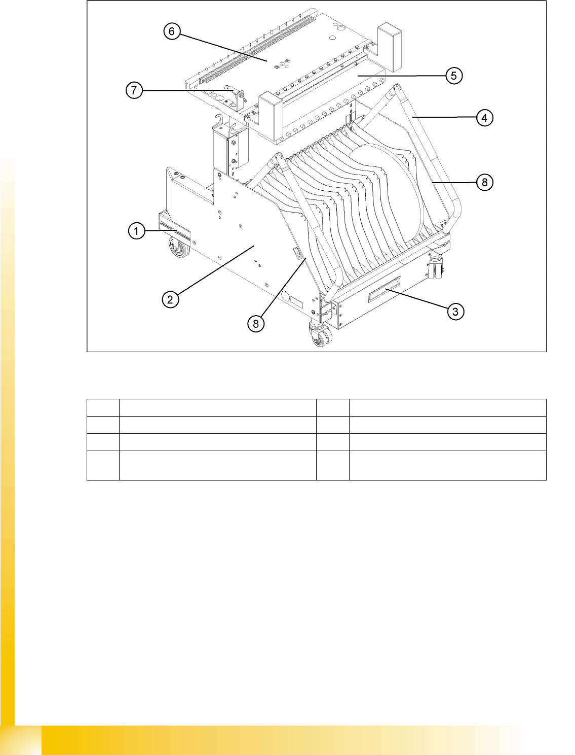
9.1.3 Changeover Table
9-2: Overview: Changeover table structure (D1/D2 shown as example)
Legend
1 Moveable base with fixed and guide castor 5 Communication unit
2 Tape reels container 6 Table plate
3 Tape waste container 7 Switch for lowering the changeover table
4 Handle 8 Storage room for extra partition plates or setup
lists, next to the handles