D-serie LEVEL II.pdf - 第156页
Component Handling Optional Extension on the COT Holder for the Third Tape Reel on 3 x 8 mm S Feeder Modules S tuden t Guide Advanced Level 2 SIPLACE D Series Component Ha ndling EN 05/2007 9-6 9.3 Optional Extension on …
Component Handling
Adjusting the Component Trolley Height Setting the Height of the Changeover Table
Student Guide Advanced Level 2 SIPLACE D Series
EN 05/2007 Component Handling
9-5
9.2 Setting the Height of the Changeover Table
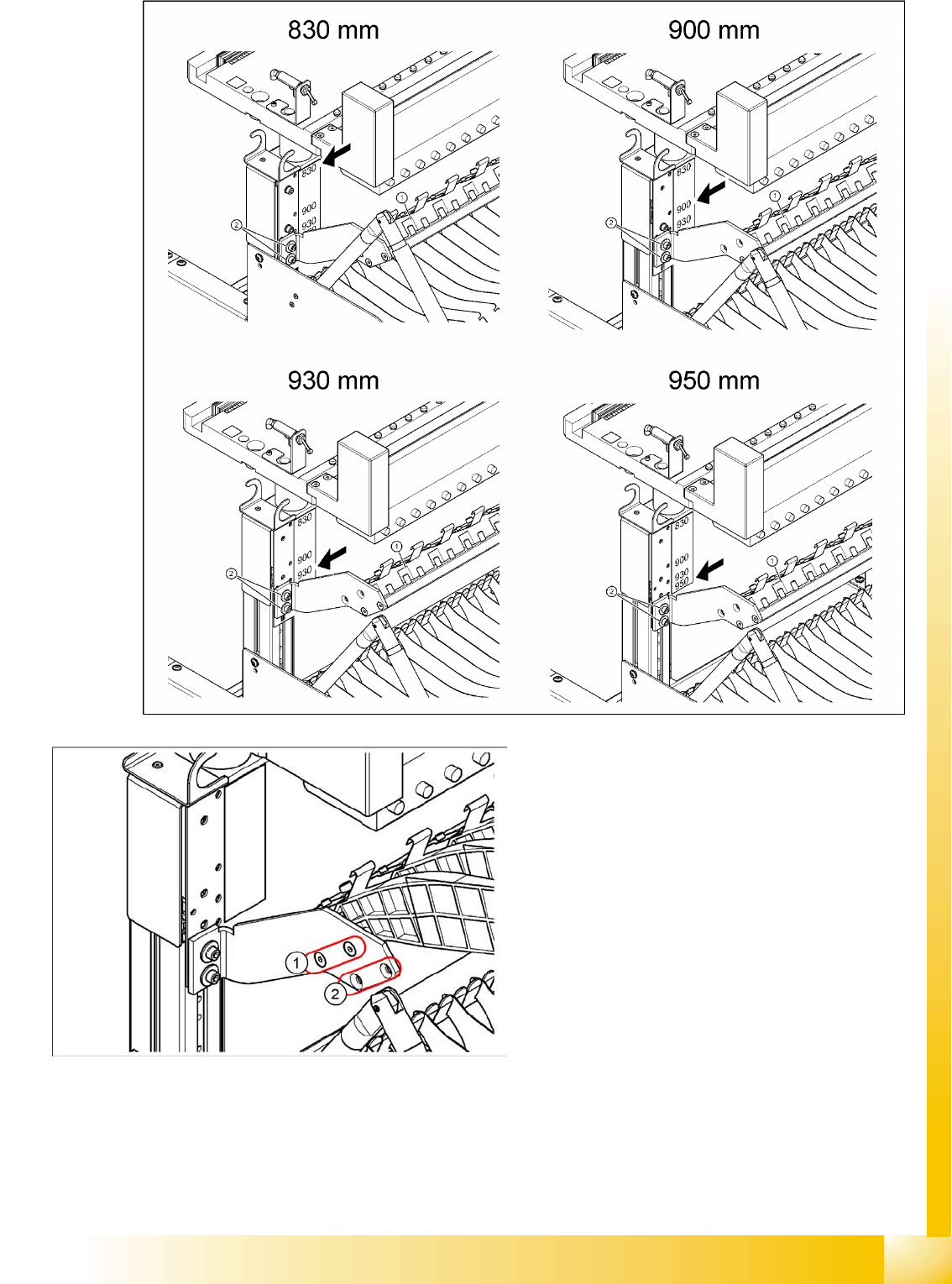
The changeover table can be manually set to the following PCB transport heights
830 mm PCB transport height
900 mm PCB transport height
930 mm PCB transport height
950 mm PCB transport height
9.2.1 Adjusting the Component Trolley Height
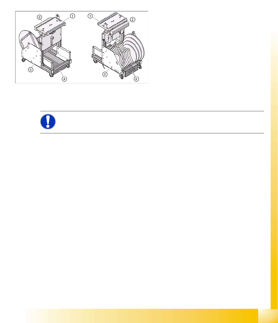
9-3: Changeover table (D4 shown as example)
Legend
1. Feeder table plate
2. Communication unit
3. Tape container
4. Waste container for tape cuttings
NOTE:
For details of the procedure for changing the component trolley height, refer to the service
manual for the relevant machine.
Component Handling
Optional Extension on the COT Holder for the Third Tape Reel on 3 x 8 mm S Feeder Modules
Student Guide Advanced Level 2 SIPLACE D Series
Component Handling EN 05/2007
9-6
9.3 Optional Extension on the COT
When using these options, do not forget that the D1/D2 and D4 machines have different table widths.
9.3.1 Holder for the Third Tape Reel on 3 x 8 mm S Feeder Modules
The following parts are needed for the middle tape reel:
An adapter plate to hold the tape reel holder (1)
One tape reel holder for every two feeder modules (2).
The adapter plate is fixed with four fillister head screws to the component trolley, while the tape reel
holder is plugged into the square openings in the adapter plate.
Installation position of adapter plate
Due to the various machine heights, D machines have four different installation positions for the holder
of the third tape reel (adapter plate).
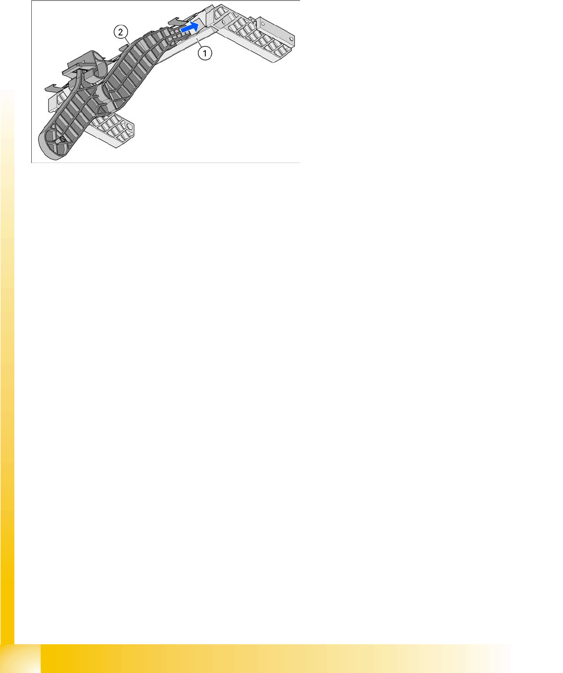
9-4: Holder for middle tape reel in 3 x 8 mm S feeder modules, with D3 shown
as example (the diagram does not show the actual installation position in the
changeover table - the side part of the adapter plate (1) is vertical there).
Legend
1. Adapter plate
2. Tape reel holder
Feeder modules of type 3 x 8 mm-S transport
components in three feeder tracks to the pickup
position. The tape reels on the two outer tracks are
located between the divider sheets in the tape
container. The middle tape reel is located above
the two tape reels for the outer tracks.
Component Handling
Holder for the Third Tape Reel on 3 x 8 mm S Feeder Modules Optional Extension on the COT
Student Guide Advanced Level 2 SIPLACE D Series
EN 05/2007 Component Handling
9-7
Legend
1. Adapter plate installation position without
splice detection
2. Adapter plate installation position with splice
detection