D-serie LEVEL II.pdf - 第183页
Modular Conveyor Light Barrier Functions in Input, Output and Intermediate Conveyors Conveyor Settings S tude nt Guide Advanced Level 2 SIPLACE D Series EN 05/2007 Modular Conveyor 10-17 10.3.3 Light Barrier Functions in…
Modular Conveyor
Conveyor Settings Functions in the PCB Conveyor
Student Guide Advanced Level 2 SIPLACE D Series
Modular Conveyor EN 05/2007
10-16
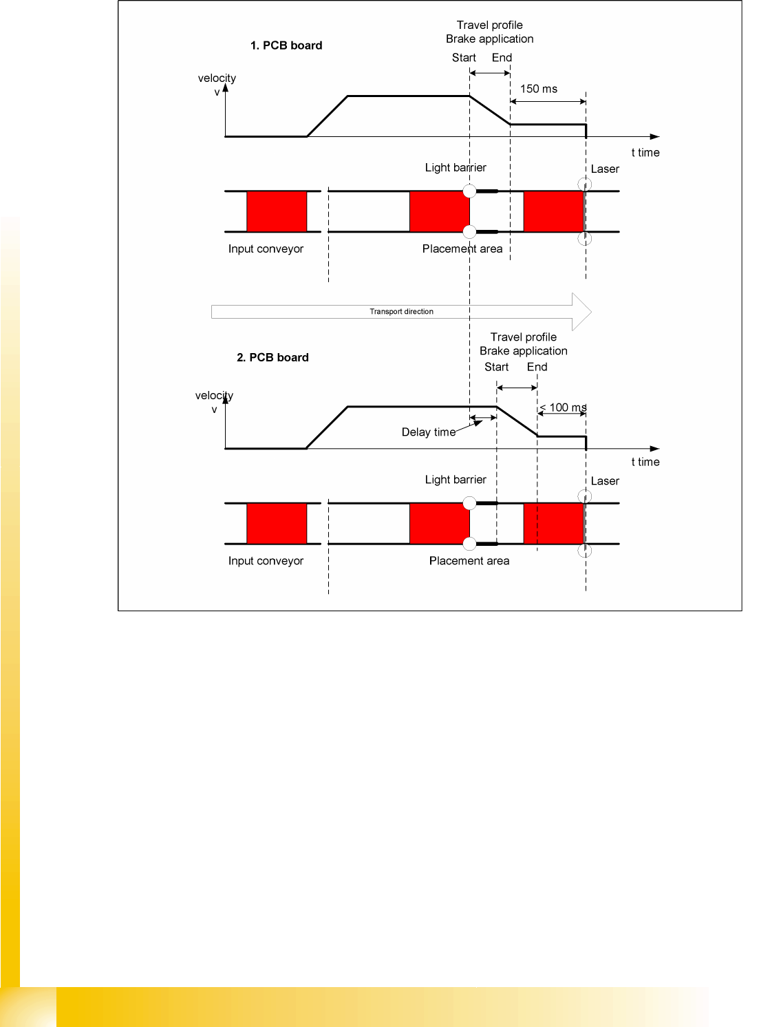
10.3.2.2 "Constant Transport Times Within Placement Area" Function
10-7: Diagram of board braking procedure
The automatic teaching at the beginning of the travel profile means that the stopper position is always
reached in the same time, irrespective of the board weight. This ensures that the transport time remains
constant.
Function of light barrier in the placement area
Laser light barrier activates
Board braking procedure starts
The light barrier in the placement area is responsible for initiating the braking procedure (travel profile)
via the conveyor software, once the board has been recognized. The software automatically "learns" the
first board by moving it in slow speed. The travel profile for braking the board is started at the right time,
to ensure that the board is reliably stopped at the laser light barrier, after a maximum of 100 ms.

Modular Conveyor
Light Barrier Functions in Input, Output and Intermediate Conveyors Conveyor Settings
Student Guide Advanced Level 2 SIPLACE D Series
EN 05/2007 Modular Conveyor
10-17
10.3.3 Light Barrier Functions in Input, Output and Intermediate Conveyors
Boards are recognized reliably and stopped
Boards are monitored in the input conveyor, meaning that
If a board is recognized in the input conveyor, it will appear on the user interface and the machine
will stop the conveyor interface to the predecessor station. When using boards with cutouts, although
the board stops, the light barrier may sometimes be deactivated again and the interface to the
predecessor station reopened. In this case, the next PCB would be transported onto the board
already lying on the input conveyor. To prevent this, the board monitoring system moves the new
board backwards again and then forwards until the light barrier switches.
Modular Conveyor
Conveyor Settings Board Recognition - Function
Student Guide Advanced Level 2 SIPLACE D Series
Modular Conveyor EN 05/2007
10-18
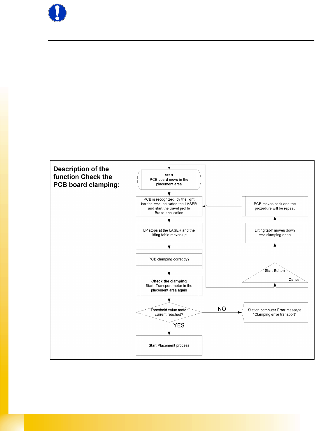
10.3.4 Board Recognition - Function
Functional description:
The board moves into the placement area, is recognized by the light barrier and stopped at the laser,
before the lifting table moves upwards.
PCB clamping check: The conveyor motor in the placement area is restarted. If the board is clamped
into place, the motor current will exceed a certain value. If the board was correctly clamped, the
placement process will begin.
If the threshold value is not reached, the system will assume that the board has moved towards the
intermediate or output conveyor and has therefore not been clamped correctly into place.
The station computer will issue the error message "Board not clamped correctly PA1 (PA2)". The
operator can try the procedure again by pressing the START button.
The lifting table will move down again, the board will be conveyed back and will approach the stopper
position once more.
NOTE:
The check to see whether a board has been correctly clamped into place is performed by adding
together the conveyor motor currents during a defined period. To check whether this function is
performed correctly, place a spacer under the side to prevent the lifting table moving upwards.
This check is not performed if the "Vacuum Tooling" option is installed.