D-serie LEVEL II.pdf - 第185页
Modular Conveyor Conveyor Control Conveyor Settings S tude nt Guide Advanced Level 2 SIPLACE D Series EN 05/2007 Modular Conveyor 10-19 10.3.5 Conveyo r Control 10.3.5.1 TSP 201 Overview TSP 201 Legend NOTE: The TSP201 c…
Modular Conveyor
Conveyor Settings Board Recognition - Function
Student Guide Advanced Level 2 SIPLACE D Series
Modular Conveyor EN 05/2007
10-18
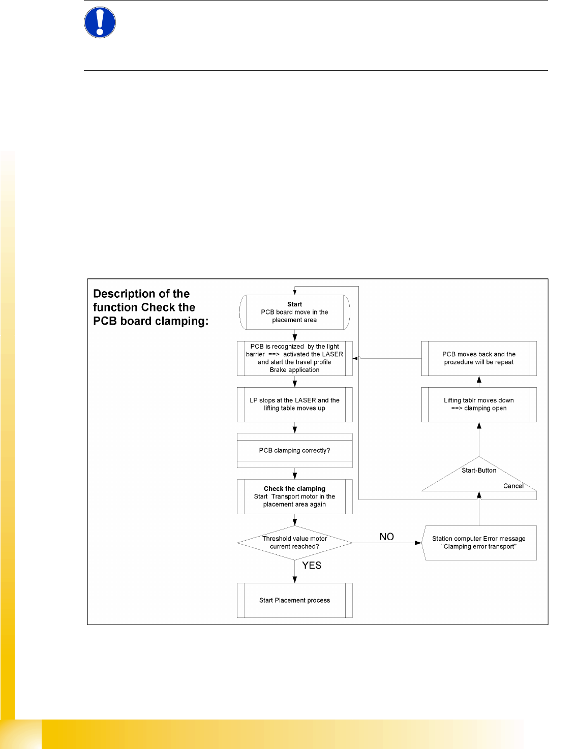
10.3.4 Board Recognition - Function
Functional description:
The board moves into the placement area, is recognized by the light barrier and stopped at the laser,
before the lifting table moves upwards.
PCB clamping check: The conveyor motor in the placement area is restarted. If the board is clamped
into place, the motor current will exceed a certain value. If the board was correctly clamped, the
placement process will begin.
If the threshold value is not reached, the system will assume that the board has moved towards the
intermediate or output conveyor and has therefore not been clamped correctly into place.
The station computer will issue the error message "Board not clamped correctly PA1 (PA2)". The
operator can try the procedure again by pressing the START button.
The lifting table will move down again, the board will be conveyed back and will approach the stopper
position once more.
NOTE:
The check to see whether a board has been correctly clamped into place is performed by adding
together the conveyor motor currents during a defined period. To check whether this function is
performed correctly, place a spacer under the side to prevent the lifting table moving upwards.
This check is not performed if the "Vacuum Tooling" option is installed.
Modular Conveyor
Conveyor Control Conveyor Settings
Student Guide Advanced Level 2 SIPLACE D Series
EN 05/2007 Modular Conveyor
10-19
10.3.5 Conveyor Control
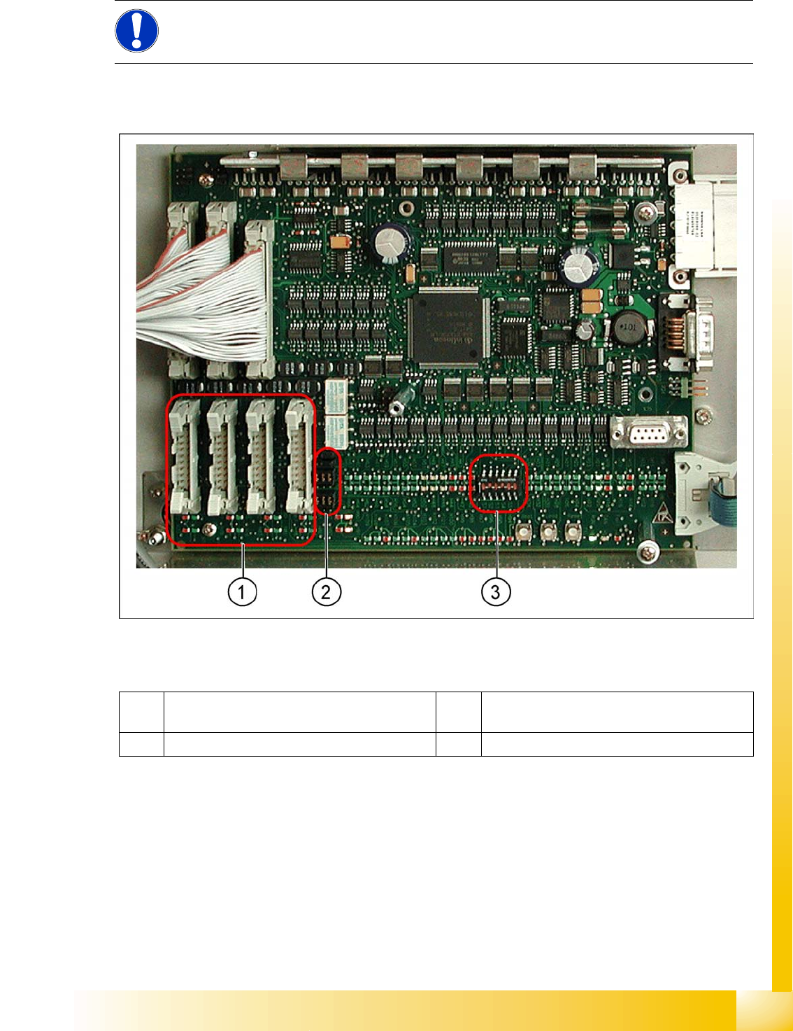
10.3.5.1 TSP 201
Overview
TSP 201
Legend
NOTE:
The TSP201 conveyor control is used in D1 and D2 machines, while TSP301 conveyor control
is used in D3 and D4 machines.
1 PCB handling (predecessor /successor
stations)
3 DIP switch for single / dual conveyors
2 Jumper for SIEMENS / SMEMA option
Modular Conveyor
Conveyor Settings Conveyor Control
Student Guide Advanced Level 2 SIPLACE D Series
Modular Conveyor EN 05/2007
10-20
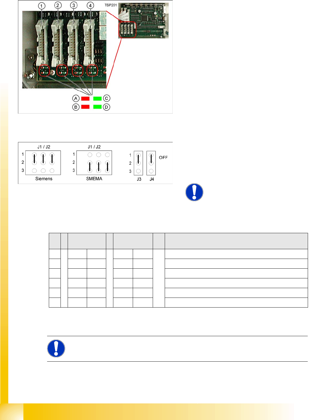
PCB Handling - Predecessor and Successor Station
SIEMENS / SMEMA
Single / Dual Conveyor
LEDs on the TSP201
Legend
1. X1 – PCB handling – predecessor station lane
1
2. X2 – PCB handling – successor station lane 1
3. X4 – PCB handling – predecessor station lane
2
4. X5 – PCB handling – successor station lane 2
Connector and interface status display
A = Received
B = Permitted
C = Transmitted
D = Requested
10-8: Jumper J1, J2 "successor/predecessor station" at TSP 201
Legend
J1 predecessor station
J2 successor station
J3/J4 interference loop
NOTE:
Jumpers J1 and J2 can be set
independently of one another, at
SIEMENS or SMEMA.
S Single
conveyor
Dual conveyor Note
1OFF ON OFF = single conveyor, ON = dual conveyor
2ON ONStation type (always ON)
3OFF OFF OFF = clamping sensor deactivated
4ON ONOFF = 125 Kbit/s (S27), ON = 1 Mbit/s (D1/D2)
5oo oo CAN terminating resistor , OFF for D1, ON for D2
6OFF OFF Not used
DIP switch S1 on TSP201
NOTE:
See also the label on the TSP201 cover.