D-serie LEVEL II.pdf - 第208页
SITEST Calibration Basics Component Camera S tuden t Guide Advanced Level 2 SIPLACE D Series SITEST EN 05/2007 12-8 Sequence segment offset top (I): 12-1: Principle picture of a calibration tool in the came ra in 0° (lef…
SITEST
Travel Range Calibration Basics
Student Guide Advanced Level 2 SIPLACE D Series
EN 05/2007 SITEST
12-7
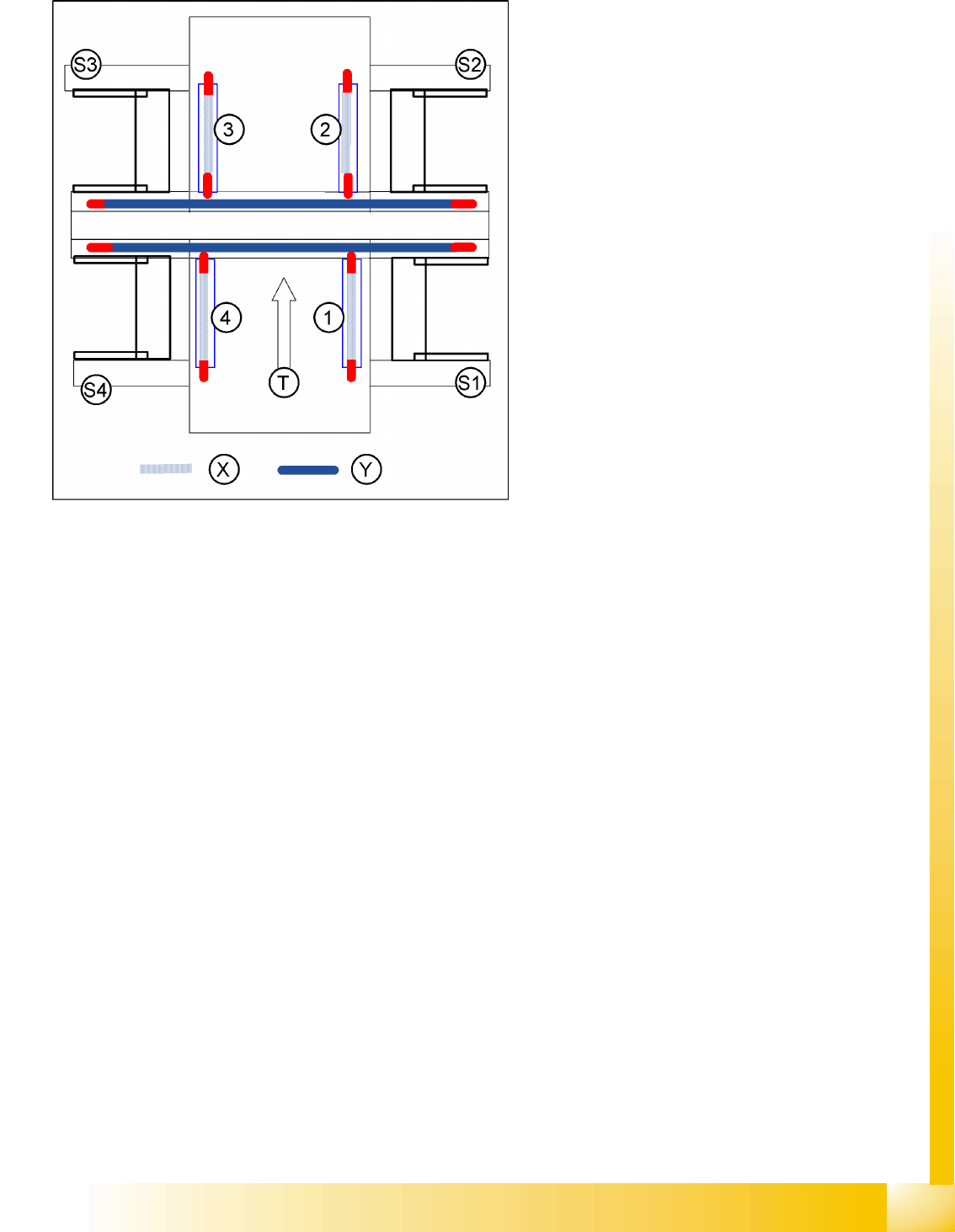
12.2.4 Travel Range
12.2.4.1 Position of Calibration Tool
Calibrate the X and Y pick up position of the calibration tool.
12.2.5 Component Camera
The Pixel size of the CCD sensors of the camera is determined in µm. Measured and calculated with
Ax/Bx/Cx/Ay/ByCy calibration values. Saved in
camera.xml
as: XU_Pixel / YU_Pixel in nm
The pixel size is:
approx. 49700 nm for component camera SST 28 (for 12-segment head)
approx. 26760 nm for component camera SST 29 (for 6-segment head/12-segment head option)
approx. 17220 nm for component camera SST 23 (for 20-segment head)
The camera center is determined.
The Mounting angle of the CCD-chip in the camera to the turning level of the placement star is
measured. The value is saved as Kamera_winkel (camera_angle) in the data block of the component
camera, in the
camera.xml
.
X gantry axis:
The X gantry axis moves to the zero pulse, to
calibrate the travel range and then moves on
to the HW end stoppers (limit switch). The
respective gantry axis position is recorded
there.
The maximum hardware travel range is set 1.5
mm before the bumper. The software travel
range value is 0.5 mm before that.
Y gantry axis:
The Y gantry axis moves to the zero pulse, to
calibrate the travel range and then moves on
to the outer HW end stoppers on the left or
right (limit switch). The respective gantry axis
position is recorded there.
The maximum hardware travel range is set 1.5
mm before this position. The software travel
range value is 1.5 mm before that.
In the case of the Y axes, only the outer HW
end stoppers are approached in each case.
The other end position of the travel path is
calculated. This gives a travel range distance
to the other gantry of about 35 mm.
Legend
1-4:Gantry 1-4
S1 - S4:Sector 1-4
X:Travel range X
Y:Travel range Y
T:Transport direction
SITEST
Calibration Basics Component Camera
Student Guide Advanced Level 2 SIPLACE D Series
SITEST EN 05/2007
12-8
Sequence segment offset top (I):
12-1: Principle picture of a calibration tool in the camera in 0° (left); in 180°(right).
PCB Camera - Component Camera Offset:
During measurement of the segment offset up (I), the calibration of the PCB camera -> component
camera offset is performed with segment 1:
The distance in X- and Y- direction of the camera centers is determined in µm.
The top segment offset (I) is compared to a calculated average value. (the segment offset I of
segment 1 is therefore no longer 0.)
Segment 1 is the reference point for calculation of the offset (I and II).
This distance is saved in REAL.MA at ‘Kopfoffsets’ at Kopf 1 Kopfoffset_X /..Y. The segment offset
down (II) for segment 1 is 0 (see below).
The segment offsets for the remaining 11 segments are saved in the PIP_OFF.MA file (as deviation
to segment 1).
Deviation in the X and Y direction of the rotary axis for the remaining segments, compared to
segment 1 (in µm).
Measurement is performed at 0° and 180° or 90° and 270° in each case. The center of the segment
is then determined from these 0/180° or 90/270° values.
The values for the segment offset are saved in the PIP_OFF.MA file.
Sequence segment offset bottom (II):
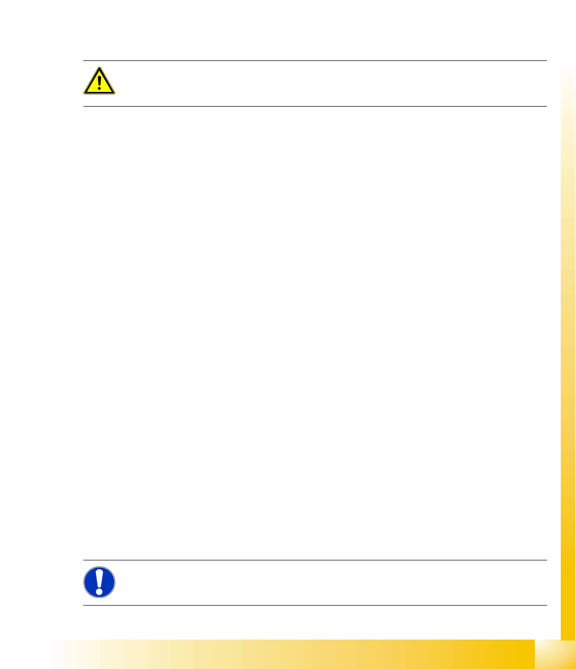
12-2: Sequence at one nozzle:
After the segment offset up (I) calibration step has been performed, the calibration procedure for the
segment offset down (II) begins for C&P DLM 3:
Is the calibration tool picked with a Nozzle under 0 degree; optically centered and placed with the
PCB-camera is the exact placement position determined (in µm).
ATTENTION:
For the segment offset I (top), the standard deviation value should not exceed 600 µm. The
difference between the segments must not exceed +/- 150 µm.
Segment offset II (down) absolute threshold +/- 150 µm and difference in values max. +/-
150 µm.
NOTE:
The segment offset II (bottom), from the first segment is always 0 that is the reference value to
the other segments.
SITEST
Nozzle Changer (C&P Head) Calibration Basics
Student Guide Advanced Level 2 SIPLACE D Series
EN 05/2007 SITEST
12-9
Is the calibration tool picked with a Nozzle under 90 degree; optically centered and placed with the
PCB-camera is the exact placement position determined (in µm).
Is the calibration tool picked with a Nozzle under 180 degree; placed with the PCB-camera is the
exact placement position determined (in µm).
Is the calibration tool picked with a Nozzle under 270 degree; placed with the PCB-camera is the
exact placement position determined (in µm).
This sequence is repeated. From the 8 placement positions is the average value of the place.
Deviation calculated and taken for the seg. offset.
12.2.6 Nozzle Changer (C&P Head)
Each nozzle magazine has a fiducial which will recognize during the calibration procedure at first.
optional, calibrate the pick up height from the nozzle changer.
optional, calibrate the reject position from the nozzle changer, necessary to reject nozzle which are
defect.
12.2.7 Calibrating and Teaching Machine Positions
New function for calibrate the positions is the teach menu before calibrate, so that you can teach the
correct position for a successful calibration.
12.2.7.1 Conveyor Sides
This new calibration procedure is necessary for the modular conveyor system.
With the modular conveyor are all conveyor sides adjustable. For adjustment the conveyor sides we use
one stepping motor which is connected via a toothed belt to the adjustment unit. The position of the
conveyor side is recognized by a proximity switch, meaning that there is a switching point for each
conveyor side. With this calibration the switch points are optimized of the entire travel range of the width
adjustment. Calibration is required to ensure that the two positioning drives move the conveyor sides
parallel to one another.
Automatically Sequence (Transport mapping):
Initialize the positioning drive, move to the right side (limit switch)
The positioning drive recognizes the fixed conveyor side(s) (two for dual conveyor) and moves the
flexible conveyor side(s) to the standard position of 55 mm and then accurately measures the
position set.
The positioning drive moves the conveyor side(s) step-by-step (10 mm steps) and determines the
offset of the switching points for the proximity switches in the two positioning drives of the various
conveyor side positions.
This calibration of the side position will be done for width adjustment wider and smaller.
The results are saved in the TSP 301 (TSP 201) as correction values and taken into account later
when setting and measuring the conveyor width.
ATTENTION:
Before starting calibration of the nozzle changer, check the nozzle changer configuration and
the component level.
NOTE:
Calibration needs to be performed for lanes 1 and 2.