D-serie LEVEL II.pdf - 第212页
SITEST Calibration Basics Head Mapping (C&P H ead) S tuden t Guide Advanced Level 2 SIPLACE D Series SITEST EN 05/2007 12-12 The results will be saved in the file MAPP_xy.MA (x= gantry number, y= conveyor la ne). 12.…
SITEST
PCB Mapping Calibration Basics
Student Guide Advanced Level 2 SIPLACE D Series
EN 05/2007 SITEST
12-11
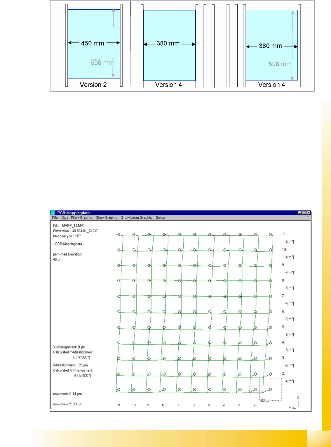
12-4: Position mapping plate and conveyor side position for single and dual conveyor
12.2.8.2 Procedure:
X Place the mapping disk or CD-ROM in the station computer and copy the measurement data for this
mapping plate.
X Put the mapping plate in the input conveyor for placement area 1 or in the intermediate conveyor for
placement area 2.
X Now appears the teach menu to teach the fixed PCB corner OK.
X PCB mapping is running.
X Then the gantry axes move the camera up to the start position. The light-colored fiducial cross will
now be centered with the help of a synthetic image.
X This results are set for the nominal coordinates. 40.000 µm in X- respectively Y- direction added for
the next fiducial nominal position.
X The deviation of the structure to this theoretical position is measured.
12-5: Result of PCB mapping
SITEST
Calibration Basics Head Mapping (C&P Head)
Student Guide Advanced Level 2 SIPLACE D Series
SITEST EN 05/2007
12-12
The results will be saved in the file
MAPP_xy.MA
(x= gantry number, y= conveyor lane).
12.2.9 Head Mapping (C&P Head)
Head mapping measures the linearity of the C&P head X/Y guidance.
The C&P head places the calibration tool precisely on the default positions of the mapping plate. The
PCB-camera measure the placement accuracy of this placements for the whole placement area.
After the PCB mapping the placement head place at the theoretical positions of the PCB-mapping
the calibration tool.
The PCB camera measures the placement accuracy with the help of the 4 calibration tool fiducials
on the calibration tool upper side.
12.2.10 New Functions in SITEST
12.2.10.1 Transport Menu
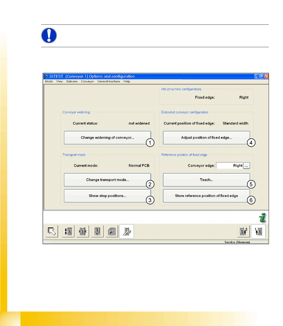
12-6: Transport - option and configuration
Legend
1.
Changing the conveyor width
(only for lane 1, if dual conveyor):
You will see a submenu, in which you can select
Widened
or
Not widened
(standard width).
Widened means that lane 2 is moved together (to the limit switch), while the fixed side for lane 1
remains in its position. (max. width of lane 1 = 380 mm)
If point 4 is selected first (extra wide) this gives a max. width for lane 1 of 430 mm.
NOTE:
All described automatically calibration steps above, can you do manually step by step under the
sub menus (see chapter 12.1).
SITEST
New Functions in SITEST Calibration Basics
Student Guide Advanced Level 2 SIPLACE D Series
EN 05/2007 SITEST
12-13
2.
Change transport mode
:
This function is used to configure the option
Long Board
.
Next menu:
normal PCB/ long PCB
3.
Show stop positions
:
shows the number of position in PA 1 and PA2, additional the offset depend on the standard position
(PCB Reference- corner). The offset for the option
Long Board
is set by SIPLACE Pro.
4. This enables you to move the fixed conveyor side in its standard position to accommodate standard
or extra wide boards (values from the conveyor control machine data).
Extra wide means that the fixed side is moved up to 26 mm. (dual conveyor lane 1 and lane 2 =
242 mm, flexible dual conveyor lane 1 = 430 mm, single conveyor = 508 mm)
5. Point 5 and 6 only with Siemens Service password active! The fixed conveyor side (
left, right
) can
be taught.
6. Save the teach data from point 5.
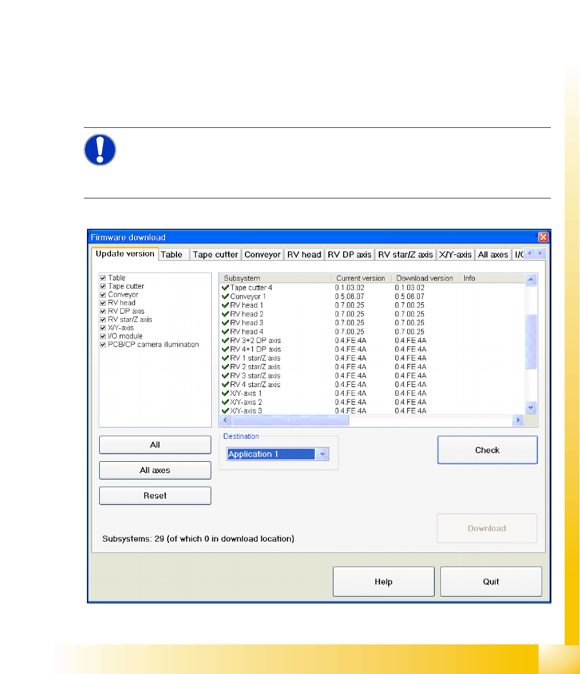
12.2.10.2 Function Firmware Download
X , select
Settings
from the SITEST menu and then
FirmwareDownload
.
12-7: Overview of firmware download
NOTE:
For versions up to SC/MC SW 603, this function is only available to SIEMENS service
personnel.
From SC/MC SW 604, the downloads performed with SITEST to all components can also be
executed by customer service technicians.