D-serie LEVEL II.pdf - 第22页
Operational Safety ESD Guidelines Safety and signaling circuit S tuden t Guide Advanced Level 2 SIPLACE D Series Operational Safety EN 05/2007 2-6 – 40 VDC operating voltage is swit ched to the comp onent trolleys. – 24 …

Operational Safety
Safety and signaling circuit Safety Equipment
Student Guide Advanced Level 2 SIPLACE D Series
EN 05/2007 Operational Safety
2-5
The color of all individual wires, which still carry potentially lethal voltages even if the main power
switch is switched off, is brown.
– Death, serious injury or considerable damage may result if these automatic placement systems
are handled incorrectly.
– Always follow the applicable accident prevention and DIN regulations (particularly DIN EN 60
204, part 1) and the applicable regulations in your own country.
– The safety door to the power supply must ONLY be opened by appropriately qualified and
trained personnel.
EMERGENCY STOP pushbutton, latching, with override protection to EN 418
The emergency stop button is red and latches in the ON position when pressed. When pressed, the
emergency stop button opens the switching contact of the emergency stop circuit - the protective
contactor combination (PCC K1) triggers. The link voltage (200 VDC) for the gantry axes and the link
voltage (150 VDC) for the star axes is switched off. The servo amplifiers for the DP and Z axes are still
supplied with 40 VDC. The signaling contact of the EMERGENCY STOP button will open and the
message
EMERGENCY STOP operated
will be shown on the screen. The following assemblies will
be disabled:
PCB conveyor
PCB clamping
Width adjustment
PCB stopper
Empty tape cutter.
See also:
J 2.4.2.1 Safety Circuit Function [J2-5]
2.4.2 Safety and signaling circuit
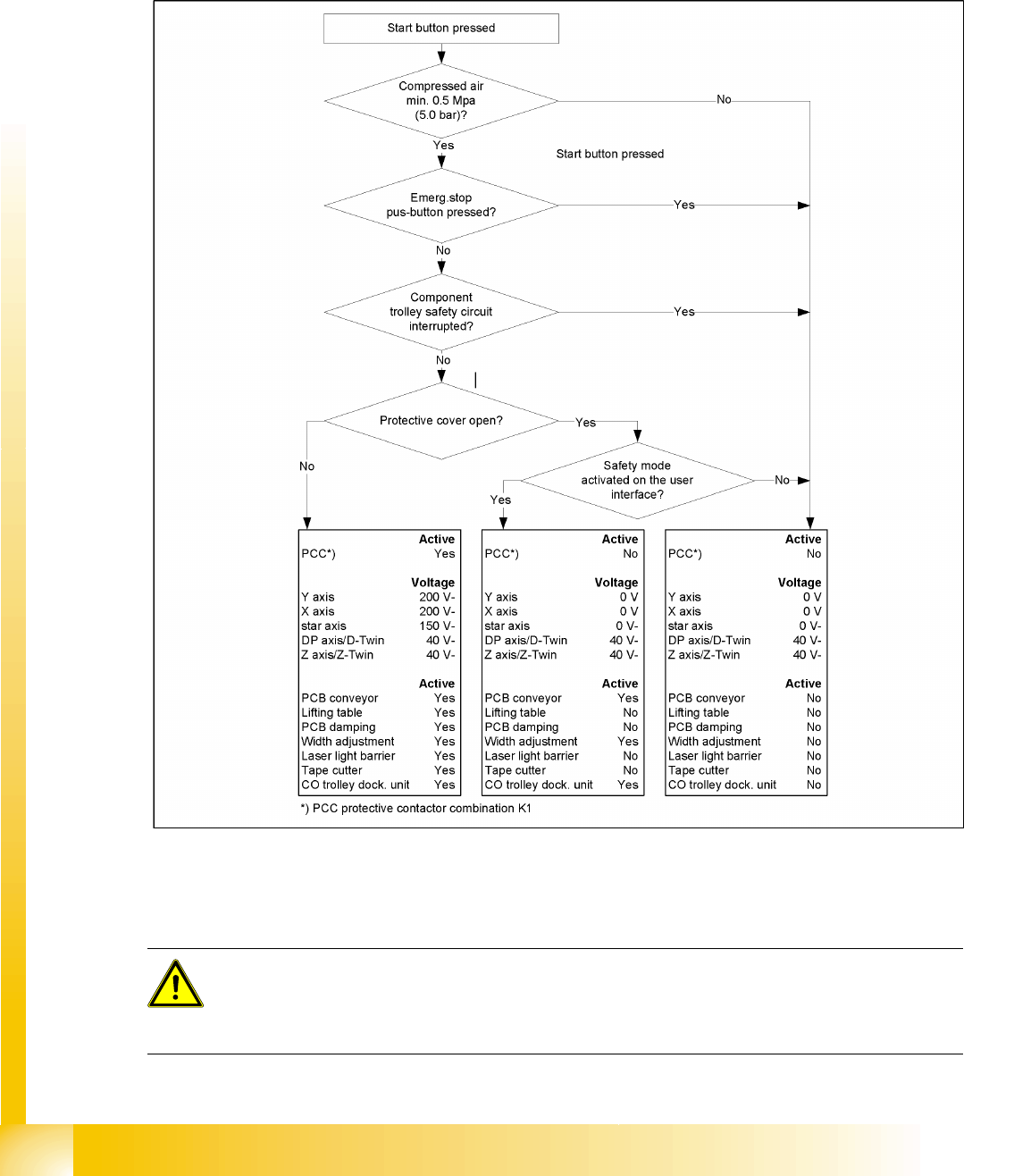
2.4.2.1 Safety Circuit Function
The following conditions must be fulfilled in order to start and operate the placement machine:
All four component trolleys must be docked in and connected.
All protective covers must be closed.
The two cover flaps over the PCB conveyor must be closed.
Both emergency stop buttons must be released.
The cover flaps (option) over the feeder modules must be closed.
The minimum operating pressure must have been reached.
The "software enable" signal must be active. This ensures that the safety circuit is closed.
The power supply must be sending 24 V to the Start buttons and the protective contactor
combination.
If one of the start buttons is pressed now, the protective contactor combination PCC K1 will switch
and enable the following components:
– 200 VDC link voltage for the servo amplifiers for the gantry axes
– 150 VDC link voltage for the star axes
– The axis unit receives a "Servo enable" signal for the servo amplifiers
NOTE:
Placement will be interrupted and can then be continued or canceled once the machine is
functional again.
Operational Safety
ESD Guidelines Safety and signaling circuit
Student Guide Advanced Level 2 SIPLACE D Series
Operational Safety EN 05/2007
2-6
– 40 VDC operating voltage is switched to the component trolleys.
– 24 VDC operating voltage is switched to the empty tape cutters.
– The PCB conveyor control receives the enable signal for the PCB clamping, the PCB stopper
and the lifting table control.
The machine is then ready for use.
2.4.2.2 Safety Loops
2-4: Safety loops
2.5 ESD Guidelines
ATTENTION: See operating manual
The ESD guidelines apply for all work to and with the electronic assemblies of your own and the
training machine. For more details about the ESD guidelines, refer to the operating manual for
the relevant SIPLACE machine.

Operational Safety
Safety and signaling circuit Room for Your Sketches and Notes
Student Guide Advanced Level 2 SIPLACE D Series
EN 05/2007 Operational Safety
2-7
2.6 Room for Your Sketches and Notes