D-serie LEVEL II.pdf - 第222页
SITEST Calibration Steps and Individual Calibrati on Functions New Functions in SITEST S tuden t Guide Advanced Level 2 SIPLACE D Series SITEST EN 05/2007 12-22 The position of the flexible conveyor side when moving toge…
SITEST
New Functions in SITEST Calibration Steps and Individual Calibration Functions
Student Guide Advanced Level 2 SIPLACE D Series
EN 05/2007 SITEST
12-21
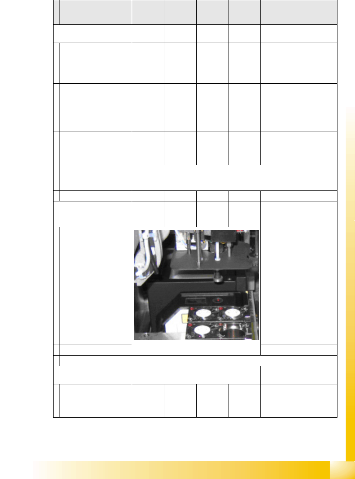
Calibrating nozzle changer
head 2
YES
With TWIN
YES In 'all heads/ cameras', in part
with Vision image
During automatic calib. the
1st fiducial is not shown to
operator for confirmation;
the pickup/place sequence
runs through to end .*
With single step, the 1st
fiducial is shown to the
operator for confirmation
Measure X/Y position of
magazines and whole
changer with PCB camera.
As single step in: 'C&P head/
RV head' 'Nozzle ch.
magazine function.' 'noz. ch.
calib.' You can select/
deselect the reject pos. /
pickup height.
The pickup height is
calculated by inserting a
5xx nozzle into an empty
garage.
TWIN module 1 must carry one nozzle and there must be one garage empty in all
the magazines. This is required for measurement in automatic mode to be
performed.
Save in PPW_ver.ma.
Calibrating coplanarity
(head 2 P&P module) (1 D
coplanarity)
YES
With TWIN
& ILD
YES
With
ILD2200
Semi-automatically in 'all
heads/ cameras' without
Vision image
After all calibrations with the
Vision CT have been
completed, the procedure
stops with 'prepare PA'.
517 nozzle
The Vision CT must be
replaced with the coplanarity
CT.
Copl. CT is picked up.
Measure on the top edge of
the conveyor side.
As single step in: 'P&P
module' 'coplanarity'
'calibrate coplan.'
The focus height of the laser
is measured.
The X/Y outer edges of the
coplanarity CT are
measured in 90° steps, to
determine the laser beam
position.
Save in coplan.ma.
Semiautomatic calibration menus or menus which are activated in single step mode.
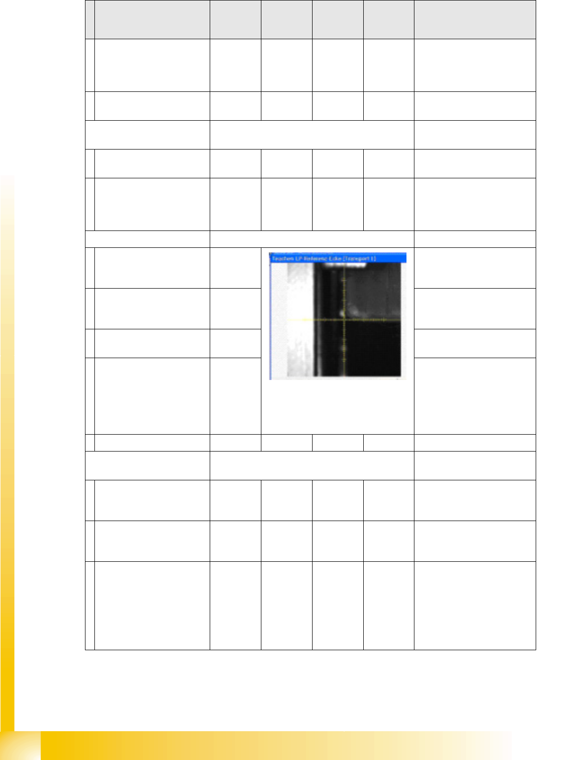
Calibrating the conveyor
sides
YES To be manually calibrated
The position of the flexible
conveyor side when moving
apart is measured in 30 (12
dual conveyor) steps.
As single step in 'conveyor'
'calibrate conveyor'
Calibration step/
individual calibration
function
For D4 For D3 For D2 For D1 Comments
SITEST
Calibration Steps and Individual Calibration Functions New Functions in SITEST
Student Guide Advanced Level 2 SIPLACE D Series
SITEST EN 05/2007
12-22
The position of the flexible
conveyor side when moving
together is measured in 30
steps.
Save in conveyor control
'backup in TSP.MA'.
Calibrating the conveyor
widths
YES
As single step in 'conveyor'
'calibrate conveyor'
Save in conveyor control. Can be manually set e.g. to
100 mm. This is then the
basis for 'conveyor width
nominal value' with tolerance.
PCB reference corner YES
Adjust conveyor width
automatically to board width
with SW e.g. 100 mm.
As single step in 'gantry'
'gantry positions'
Place the board (no need to
put it on the LB position) into
the input conveyor.
PCB is automatically moved
in and clamped into place.
The gantry positions the
PCB camera into the
currently programmed X/Y
position. The operator
teaches the new position
with the PCB camera.
When you exit the teach
menu, the data will be
accepted.
Save in REAL.MA.
Calibrating the Pickup
Position
YES
Place zero point gauge
(iron) on changeover table
1, track 1.
As single step in 'conveyor'
'calibrate conveyor'
PCB camera centers 1.5
mm drilling for the pickup
coordinates of track 1.
The pickup positions of the
different feeders are between
these coordinates.
If the WPC is recognized by
SITEST on the D1 table,
changeover table 1 will be
calibrated with track 61 and
90. If the WPC is OFF,
calibration will be performed
from track 1 to 90.
Calibration step/
individual calibration
function
For D4 For D3 For D2 For D1 Comments

SITEST
New Functions in SITEST Calibration Steps and Individual Calibration Functions
Student Guide Advanced Level 2 SIPLACE D Series
EN 05/2007 SITEST
12-23
Repeat the function for
track 90 (track 72 for D4).
For precision purposes, only
use one 'iron' per location, so
that the feeder pickup
position in the table center is
not affected.
Repeat this function for all
other changeover tables.
Save in REAL.MA.
Calibrating the closed
vacuum
For (head 2 P&P module)
YES
With TWIN
YES In 'P&P module' 'calibrate
head'
The TWIN module picks up
a 518 nozzle from the
nozzle changer.
518 nozzle
The 518 nozzle is moved to
the top edge of the
conveyor side, to measure
the vacuum.
The rubber membrane of the
518 nozzle is sealed onto the
edge of the conveyor side.
The measured vacuum is the
same as the closed vacuum
value for the C&P heads.
Save in --- …. … the closed vacuum is
measured at each reference
run.
Zero adjustment vacuum
For (head 2 P&P module)
YES
With TWIN
YES In 'P&P module' 'head board'
The air blast vacuum is
adjusted to '0'.
The compressed air supply
is disabled.
This is the real '0' state.
The vacuum difference is
measured and after
reactivation, the electronic
control valve is set to the
new 0 value.
The nozzle must not be
manually blocked/closed.
Save in control valve
EPROM
Calibrating the zero point
correction D-axis
For (head 2 P&P module)
YES
With TWIN
YES In 'P&P module' 'calibrate
head'
Replace the current nozzle
on the TWIN module with
the special calibration
nozzle, according to the SW
message.
Calibration step/
individual calibration
function
For D4 For D3 For D2 For D1 Comments