D-serie LEVEL II.pdf - 第68页
Energy and Compressed Air Supply Power Supply Unit Overview of Power Supply S tuden t Guide Advanced Level 2 SIPLACE D Series Energy and Compressed A ir Supply EN 05/2007 5-2 5.2 Power Supply Unit 5.2.1 Overview of Power…
Energy and Compressed Air Supply
Overview
Student Guide Advanced Level 2 SIPLACE D Series
EN 05/2007 Energy and Compressed Air Supply
5-1
5 Energy and Compressed Air Supply
5.1 Overview
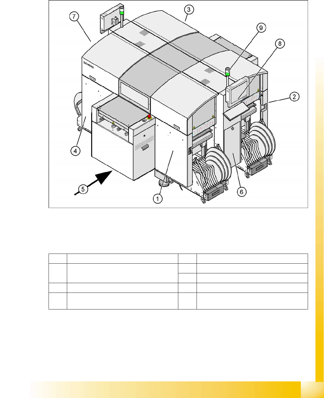
5-1: Main components in SIPLACE D4
The diagram shows where the energy supplying and distributing components for system operation are
installed:
Legend
1 Sector distributor for sector 1 5 Transport direction
2 Sector distributor for sector 2 (only by D4 on the
back of the machine)
6 Pneumatic Unit
7 Power Supply Unit
3 Sector distributor for sector 3 8 Controls (keyboard and monitor)
4 Sector distributor for sector 4 (this area is sector
2 in D1/D2)
9 Error display (right-hand machine side)
Energy and Compressed Air Supply
Power Supply Unit Overview of Power Supply
Student Guide Advanced Level 2 SIPLACE D Series
Energy and Compressed Air Supply EN 05/2007
5-2
5.2 Power Supply Unit
5.2.1 Overview of Power Supply
The main power supply unit is mounted on a compact slide-in module, and located on the left side of the
middle section. When viewed from the outside only the red main power switch is visible.
A lockable door prevents access to the power supply.
With the open cover, the state of the following protective devices can be quite easily monitored.
Motor protection switch
main contactor
Safety relay
Power circuit breaker
The following work must be performed to adjust the power supply to the country-specific requirements
(see also the conversion instructions for 3x 208 V to 3x 400 V and vice versa):
X Rewiring line supply cable/transformer
X Motor protecting switch
X Inrush current limiter connections
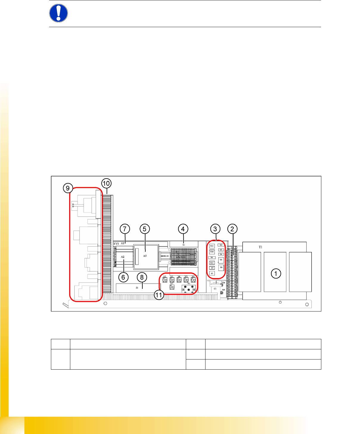
5-2: Main power supply - side view
Legend
NOTE:
Unless otherwise specified, the wiring examples shown in this section apply for SIPLACE D4
machines. Refer to the relevant circuit diagrams for all other machine types.
1 Transformer 1 7 Power supply A1 (24 V/40 A)
2 Secondary terminal strip with fuses (output
voltage T1)
8 Line filter Z1 (input voltage)
8 Line filter Z1 (input voltage)
Energy and Compressed Air Supply
Overview of Power Supply Power Supply Unit
Student Guide Advanced Level 2 SIPLACE D Series
EN 05/2007 Energy and Compressed Air Supply
5-3
3 Connector strip X2-X10, X12, X13 9 Front view (see following diagram)
4 Terminal strip X1 10 Inrush current limiter (behind the cable duct)
5 Power fail board A3
6 Power supply A2 (5 V/6.3 A) 11 Various rectifiers (V5 not in D1/D2)
5-3: Main power supply – front view (D4)
Legend
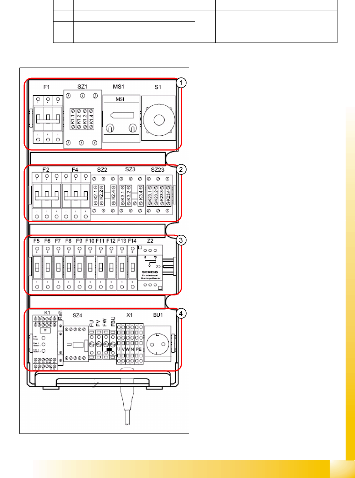
1. F1: 3x 230 V AC
SZ1: main contactor
MS1: Motor protection switch
S1: main switch
2. F2: 220 V AC for 5 V power supply
F4: 3x 140 VAC X/Y axes
SZ2,SZ3, SZ23: auxiliary contactors U,V,W for
X/Y servos
3. F5: 150 V DC star axis servo
F6: 40 V DC Z/DP axis servo
F7: 40 V DC changeover table
F8: 40 V DC PCB handling (conveyor)
F9: 8 V DC changeover table (only at D4)
F10: 48 V DC Vision illumination
F11: 24 V DC terminal strip distributor 2/4
F12: 24 V DC Microbox PC (MC)/control "ON"
(K1)
F13: 24 V DC Box PC (SR)/axis unit 1/2
F14: 24 V DC conveyor control (TSP 301)/
monitors
Z2: discharge inductor
4. K1: protective contactor combination
Relay1: control ON - button
SZ4: control ON - software
FU: fuse 6.3 AT 220 VAC to GND
FV: fuse 6.3 AT 220 VAC to GND
FW: fuse 6.3 AT 220 VAC to GND
FBU: fuse 6.3 AT 220 VAC to GND
X1: feed in - terminal strip
BU1: service socket