D-serie LEVEL II.pdf - 第77页
Energy and Compressed Air Supply Power Supply for Axis Unit Power Supply Unit S tude nt Guide Advanced Level 2 SIPLACE D Series EN 05/2007 Energy and Compressed Air Supply 5-1 1 5.2.10 Power Supply fo r Axis Unit 5-7: Po…
Energy and Compressed Air Supply
Power Supply Unit Assemblies in Sector 4
Student Guide Advanced Level 2 SIPLACE D Series
Energy and Compressed Air Supply EN 05/2007
5-10
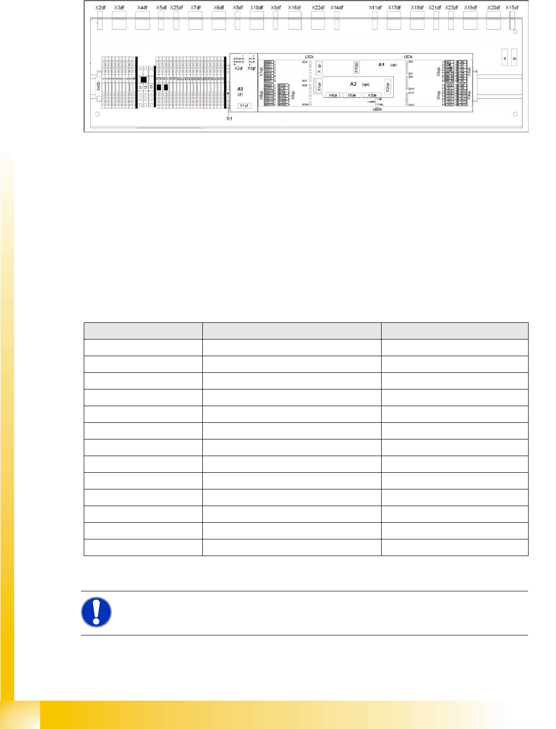
5.2.8 Assemblies in Sector 4
5-6: (diagram rotated by 90°)
Naming convention for cables and connections in sector 4
Terminal strip (voltage supply) X400
Connections (plug-in connectors) df
CAN I/O module qb
CAN interface qe
CAN Bus terminator for changeover table qf
5.2.9 Voltages in the Power Supply Unit After Switching On
When the main switch is activated, the following voltages are generated, sent to the modules and
released or held ready for release:
Voltages Module State
250 VDC X/Y servo module not enabled
150 VDC Star servo not enabled
34 VDC PCB handling system Released up to SZ2
24 VDC tape cutter not enabled
34 VDC SZ1 main power inrush current enabled
52 VDC DC/DC converter main power supply enabled
52 VDC Camera illumination enabled
40 VDC Power fail A3 enabled
42 V DC Z/DP axes enabled
40 VDC Feeder table plate enabled
28 VDC Monitor enabled
24 VDC fan enabled
230 or 115 or 240 VAC service socket independent of the main switch
NOTE:
The service socket can only be used if the placement system is connected to the main power
supply with a 5-conductor cable (L1, L2, L3, N, PE).
Energy and Compressed Air Supply
Power Supply for Axis Unit Power Supply Unit
Student Guide Advanced Level 2 SIPLACE D Series
EN 05/2007 Energy and Compressed Air Supply
5-11
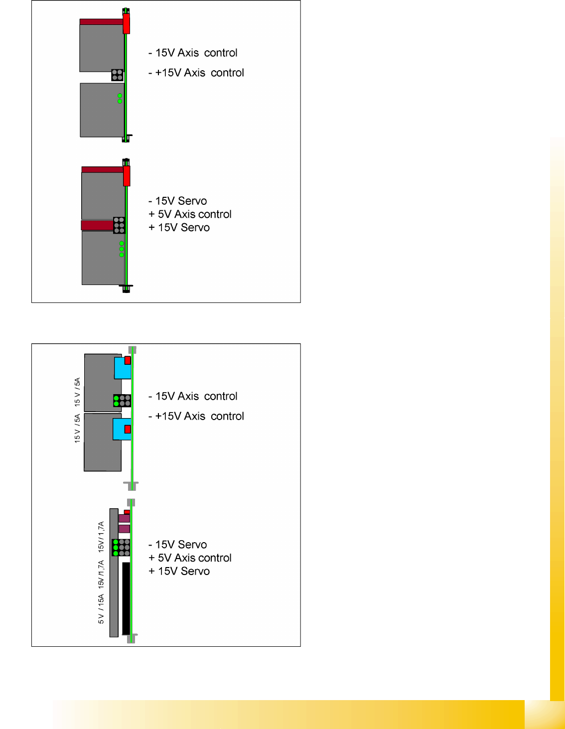
5.2.10 Power Supply for Axis Unit
5-7: Power supply for axis unit (new version)
After activating the main switch, the axis unit is
supplied with power from the main power supply,
via X8 for axis unit 1 and X9 for axis unit 2. It is
supplied with 48 VDC and the following voltages
are generated:
+/-15 V and +/-15/5 V
This DC/DC converter generates the 5V and +/-
15V needed for the servo board and the axis
controller
5-8: Power supply for axis unit (old version)

Energy and Compressed Air Supply
Pneumatic System Vacuum Generation at C&P Heads - General Information
Student Guide Advanced Level 2 SIPLACE D Series
Energy and Compressed Air Supply EN 05/2007
5-12
5.3 Pneumatic System
5.3.1 Vacuum Generation at C&P Heads - General Information
The air is supplied to the vacuum generator, which produces a vacuum using the venturi principle.
The venturi block actually consists of 2 separate venturi nozzles which produce vacuum for 2 circuits,
the holding circuit and the pick up / placement circuit.
The level of vacuum produced is dependent on a number of factors. The greatest influence on vacuum
generation is from the Venturi unit. Any leakage from or blockage within the system will result in working
inefficiently and therefore a reduction in the vacuum levels created. The Venturi unit must be absolutely
airtight and the nozzles in very good condition and of high quality.
One factor which can impair vacuum generation is the altitude. The higher above sea level a machine is
located, the low the ambient pressure will be in the room surrounding it. Therefore at high altitude low
vacuum levels are created, A SIPLACE machine in Munich, at an altitude of 500 m above sea level, can
generate a closed vacuum of approx. 870 mbar, while a machine at sea level in England would be able
to produce approx. 920 mbar.
Another factor influencing the vacuum values is the weather. Stormy, rainy days occur in periods of low
pressure. Vacuum generation during this weather may produce 880 mbar, while the same procedure a
week later, on a sunny day in a high pressure period, could well produce closed vacuum results of 900
mbar.
These 2 cases are only examples and no specific case / figures are used, but this just illustrates what
can happen. In any case, it is important that you use an efficient, high quality vacuum system.
The vacuum measurement board is located directly above the vacuum generator and measures the
vacuum values in the hold and pickup/placement circuits. Small tubes are attached to the back of the
Collect & Place head that measure the circuit pressures at the vacuum distributor. These tubes are
connected to pressure sensors. The analogue outputs of these sensors are supplied to A/D converters.
The resulting signals are then sent via the CAN-Bus to the machine controller.