D-serie LEVEL II.pdf - 第81页
Energy and Compressed Air Supply Pneumatic Unit Pneumatic System S tude nt Guide Advanced Level 2 SIPLACE D Series EN 05/2007 Energy and Compressed Air Supply 5-15 Pneumatic Unit Man ometer Supply pressure 5.3.3.2 Compre…
Energy and Compressed Air Supply
Pneumatic System Pneumatic Unit
Student Guide Advanced Level 2 SIPLACE D Series
Energy and Compressed Air Supply EN 05/2007
5-14
5.3.3 Pneumatic Unit
5.3.3.1 Overview of Pneumatic Unit
The pneumatic unit is a fixed installation inside the machine. The unit is accessible via a door and
contains the complete compressed air supply for all consumer devices.
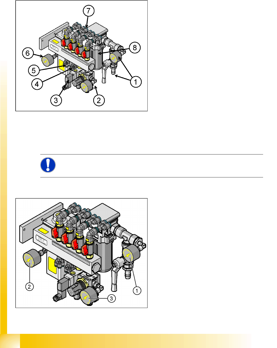
Manometer Arrangement
5-10: Pneumatic unit as rack module (D4)
Legend
1. Main compressed air connection with shutoff
valve and manometer
2. 4x connection for bulkcase feeder with
manometer, manually adjustable (2.5 bar),
location 1 - 4
3. 4x connection for cutters, location 1 - 4
2x connection for conveyor lifting table
4. 4x connection for nozzle changer
5. 4x connection for docking/undocking
changeover table
6. Electronic control valve with manometer for
incoming pressure
7. 4x connection for gantries 1 - 4, vacuum
generation C&P head with shutoff valves
8. Compressed air filter (you might need a
suitable tool to open it)
NOTE: Different pressure
Note the different pressure for the nozzle changer of the D4 machine, which is considerably
higher (5.1 +/- 0.1 bar) than that for the nozzle changers of D1/D2 machines.
5-11: Main pneumatic unit: manometer arrangement (D4)
Legend
1. Manometer input pressure (5 – 10 bar)
2. Manometer regulated supply pressure
5.0 +0.1 bar for placement heads
3. Manometer for reduced pressure 2.5 +/0.5 bar
(manually adjustable)
Energy and Compressed Air Supply
Pneumatic Unit Pneumatic System
Student Guide Advanced Level 2 SIPLACE D Series
EN 05/2007 Energy and Compressed Air Supply
5-15
Pneumatic Unit Manometer
Supply pressure
5.3.3.2 Compressed Air Distributor Block
The pneumatic unit is used to prepare and distribute the compressed air required in the machine.. The
pressure at the compressed air connection must be at least 5.5 bar.
The following pneumatic circuits are supplied with compressed air via the distributor block:
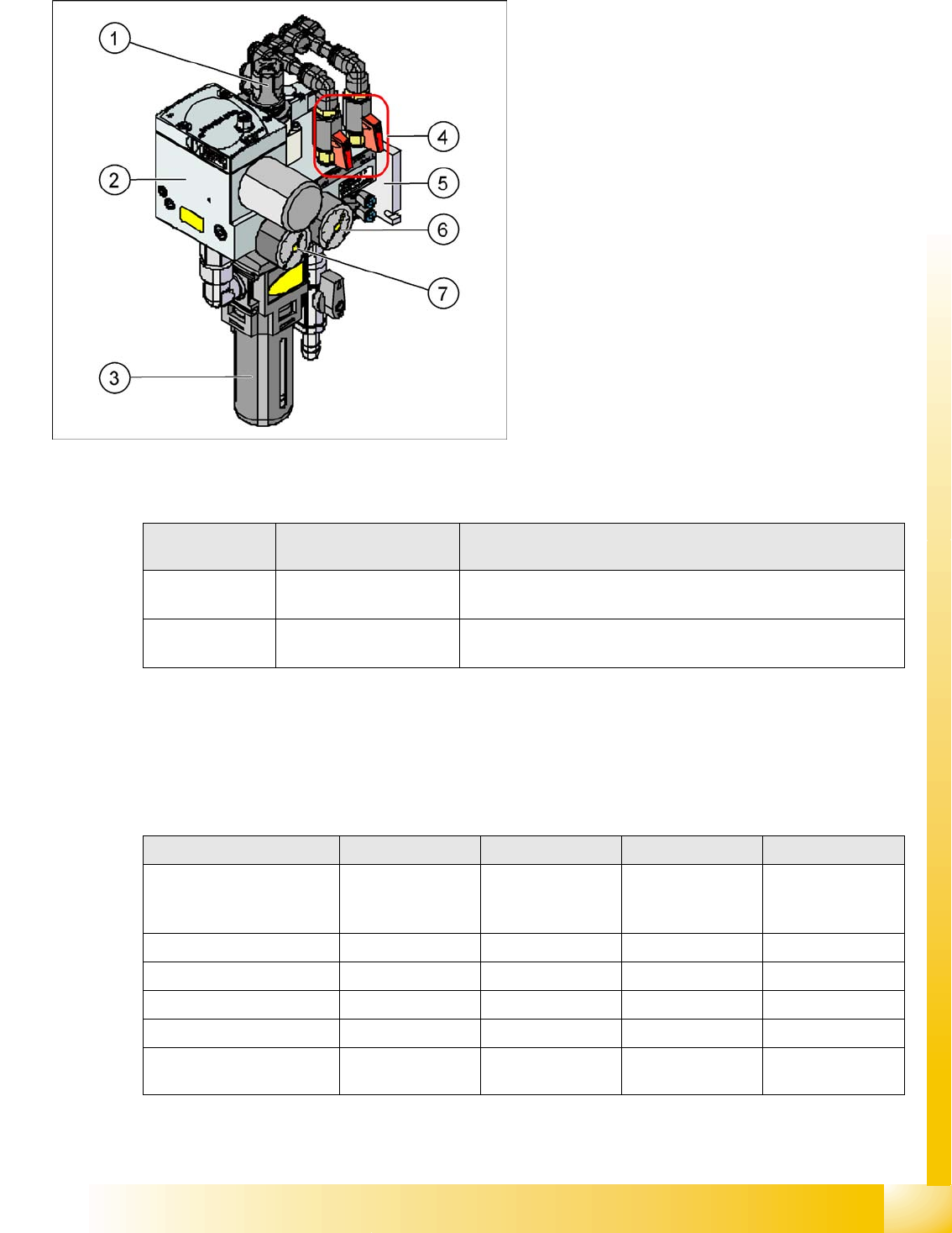
5-12: Pneumatic unit (D1/D2)
Legend
1. Manual pressure regulator for setting the
bulkcase feeder pressure
2. Centronic flange – electronic pressure control
valve
3. Compressed air filter
4. Pressure shutoff taps for gantry(ies)
5. Fixtures for pneumatic unit
6. Manometer – bulkcase feeder
7. Manometer – regulated pressure
Manometer /
Pos. No.
Target pressure Description
(6) 2.5 bar (+/- 0.5 bar)
(manually set)
For bulkcase, nozzle changerC&P6/12
(7) 5.1 (+/0.1 bar)
(electronically regulated)
For cutters, conveyor, changeover tables
For gantries (vacuum for C&P head and TWIN Head)
D4 D3 D2 D1
Gantries Vacuum
generation Placement
heads
5.1 +/-0.1 bar 5.1 +/-0.1 bar 5.1 +/-0.1 bar 5.1 +/-0.1 bar
Conveyor System 5.1 +/-0.1 bar 5.1 +/-0.1 bar 5.1 +/-0.1 bar 5.1 +/-0.1 bar
tape cutter 5.1 +/-0.1 bar 5.1 +/-0.1 bar 5.1 +/-0.1 bar 5.1 +/-0.1 bar
Nozzle Changer 5.1 +/-0.1 bar 5.1 +/-0.1 bar 2.5 +/-0.1 bar 2.5 +/-0.1 bar
Feed-in units 5.1 +/-0.1 bar 5.1 +/-0.1 bar 5.1 +/-0.1 bar 5.1 +/-0.1 bar
Bulkcase feeder Manually set 2.5
bar
Manually set 2.5
bar
Manually set 2.5
bar
Manually set 2.5
bar
Overview of compressed air supply
Energy and Compressed Air Supply
Pneumatic System Pneumatic Unit
Student Guide Advanced Level 2 SIPLACE D Series
Energy and Compressed Air Supply EN 05/2007
5-16
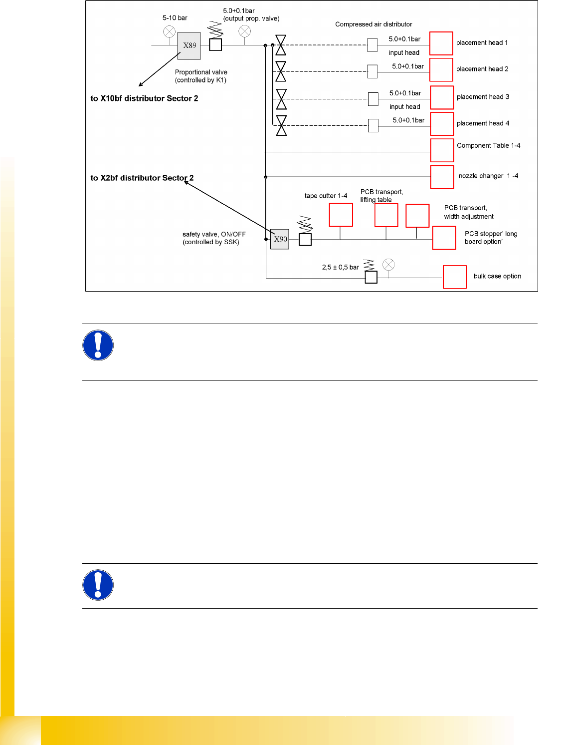
5.3.3.3 Switch ON Sequence for Pneumatic Units
5-13: Switch ON sequence for pneumatic units (example: D4)
The time for deactivation of the proportionate valve can be changed in the station software.
Settings
configure compressed air deactivation
switch off after 1-60 minutes
5.3.3.4 Main Valve X89 for Regulation of Compressed Air
After switching on the machine via the main switch, the valve is opened and compressed air flows into
the system. Opening covers, for example, has no effect on the air supply. However, if the 24 V voltage
supply fails or if the machine is switched off, the valve will close and the machine components will no
longer be supplied with compressed air. The valve is regulated via a pressure sensor. If the pressure
falls below 5.0 bar, the CAN bus will issue a signal.
NOTE:
The proportional valve X89 is enabled as soon as the machine is switched on. After performing
the reference run, the proportionate valve X89 can be switched off via the software (2 minutes
as a default).
NOTE:
This main pressure regulator can be damaged if the machine is turned on without compressed
air supplied. Therefore if the compressed air supply fails, turn of the machine.