D-serie LEVEL II.pdf - 第90页
Gantry Overview Mechanical Structure S tuden t Guide Advanced Level 2 SIPLACE D Series Gantry EN 05/2007 6-4 Y -Axis Construction 6-4: Y-Axis Design and Fan Positions (D4) Legend Additional X motor cooling is pe rformed …
Gantry
Mechanical Structure Overview
Student Guide Advanced Level 2 SIPLACE D Series
EN 05/2007 Gantry
6-3
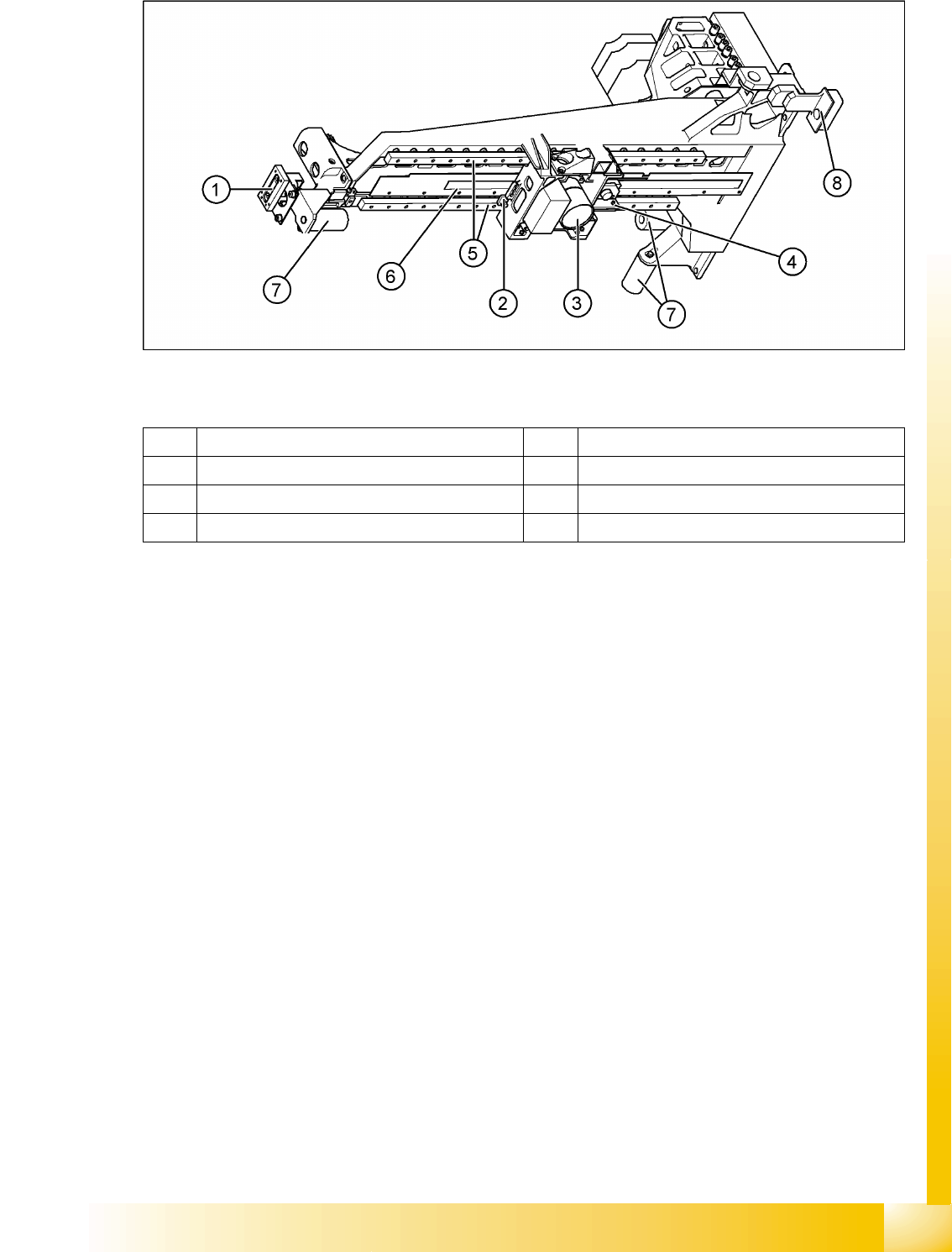
6.1.1.2 Y-Axis Mechanical Structure
6-3: Mechanical axis structure – part 2 - view from below (D4 shown as example)
Legend
Mechanical Structure
A linear motor positions the entire gantry (X-axis, head assembly plate and placement head) in the Y-
axis direction. This linear motor consists of a primary and secondary part. The secondary part consists
of permanent magnets, which are fastened lengthwise (Y direction) to the machine frame.
The primary part consists of inductors (motor windings), which are directly fastened to the gantry, in a
casing.
The drive is cooled by the compressed air supply to the placement head and also has integrated
temperature sensors, which are monitored by the axis controller.
1 Y brake 5 2x linear guide rails, each with a linear bearing
2 X brake 6 X-axis incremental scale
3 Digital PCB camera (shape varies) 7 Elastomeric spring 25x10.5x50
4 X-axis incremental encoder 8 Y-axis incremental encoder
Gantry
Overview Mechanical Structure
Student Guide Advanced Level 2 SIPLACE D Series
Gantry EN 05/2007
6-4
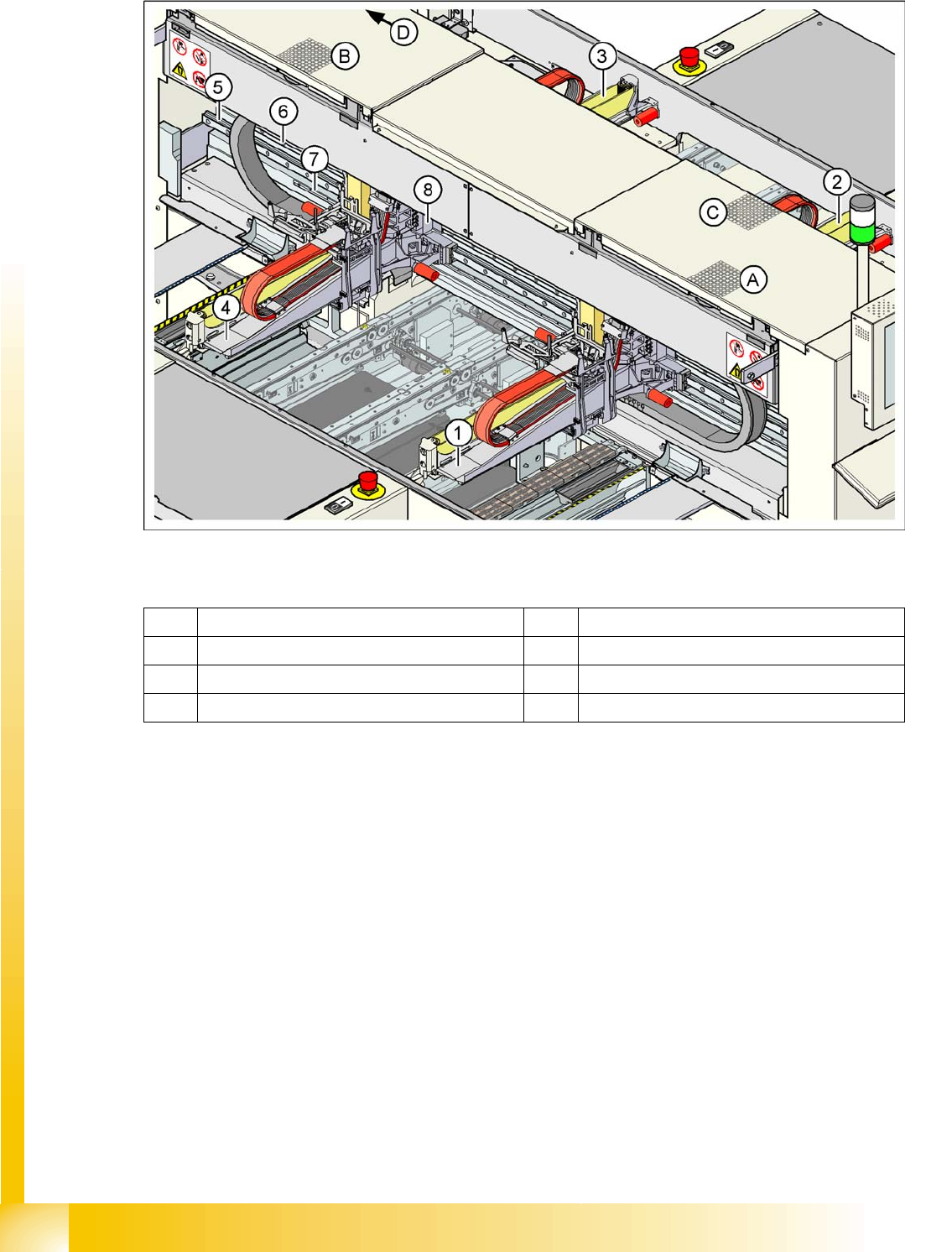
Y-Axis Construction
6-4: Y-Axis Design and Fan Positions (D4)
Legend
Additional X motor cooling is performed at the respective pickup position. The diagram above shows the
following pickup positions:
Pickup position for gantry 1 (A)
Pickup position for gantry 4 (B)
Pickup position for gantry 2 (C)
Pickup position for gantry 3 (D)
Do not cover the fan and service the filter fitted there.
1 Gantry 1 5 Guide system
2 Gantry 2 6 Linear motor secondary part
3 Gantry 3 7 Measuring system
4 Gantry 4 8 Linear motor primary part

Gantry
Overall Gantry Design Overview
Student Guide Advanced Level 2 SIPLACE D Series
EN 05/2007 Gantry
6-5
Y-Axis Technical Data
6.1.1.3 Determining the position
Incremental scales (metal) are used to determine the position of the axes. These are attached (adhesive)
between the linear guides (X axis) or under the secondary part of the Y-axis.A corresponding
incremental encoder reads the count pulses, which are transmitted to determine the position of the axes
and to regulate the axis controller board motors.
New incremental encoders with improved lens systems bring higher wanted signals for tracks A/B (V
ss
)
than previously.
Monitoring the position
Monitoring the track signals (counter edge spacing)
Monitoring the position to the travel range ends, in accordance with the speed)
Monitoring the two Y axes in one placement area
Additionally each axis has a mechanical end stop (elastomeric bumper).
6.1.2 Overall Gantry Design
The gantries on the 4 machine types in the D-series have the following common/different features:
Drive Direct, linear motor
Maximum speed 2.5 m/sec.
Travel path of gantries, calculated from the center
of the machine
Gantry 1 - 688.5 mm
Gantry 2 - 768.5 mm
Gantry 3 - 688.5 mm
Gantry 4 - 768.5 mm
Distance measuring system Incremental scale
Scale length D1/D2/D3: 1960 mm, D4: 1530 mm
Resolution 1 µm
Assembly D4 D3 D2 D1 D1 single head
Gantry Cast gantry HS CFK06 gantry X3 Extended cast gantry
X-drive Motor with belt
drive
Linear motor Motor with belt drive
X-motor cooling
(filter mats!!)
100/120 mm
fan in Y-axis
pickup position
Exhaust for
vacuum
distribution
120 mm fan in Y-
axis pickup
position, C&P
head to MA
center
120 mm fan in Y-
axis pickup
position, C&P
head on the right
in each case
120 mm fan in Y-
axis pickup
position
C&P head (right)
P&P head (left)
Temperature
sensor integrated
into motor
Cable to axis controller
X belt tension 53 Hz +1 /-3 --- 44 Hz +/-1
Incremental
encoder
With optical 1-field technology
Incremental scale Glued on metal
strips and
screwed to
gantry
Glued on an
aluminum strip
with edge guide.
This is glued onto
CFK material
Glued on gantry
Overall gantry design