D-serie LEVEL II.pdf - 第95页
Gantry Fitting the Incremental Scale Settings S tude nt Guide Advanced Level 2 SIPLACE D Series EN 05/2007 Gantry 6-9 * Equipment in addition to standard manual tools 6.2.1 Fitting the Increment al Scale 6.3 Settings For…

Gantry
Gantry Settings Pneumatic Connections on the Gantry
Student Guide Advanced Level 2 SIPLACE D Series
Gantry EN 05/2007
6-8
6.2 Gantry Settings
Assembly Tools &
equipment *
Setting type Comments See also
X-drive
X-motor D1/2 Belt tension
measuring
device
X belt is set at tensioning key to 44 +/-1 Hz
/ axis dynamics
D4 / D2/D1
measure at front
belt if the head is at
far left, against X
motor.
SA
X belt D1/2 Belt tension
measuring
device
X belt is set at tensioning key to 44 +/-1 Hz
/ axis dynamics
X deflection unit
D1/2
Belt tension
measuring
device
X belt is set at tensioning key to 44 +/-1 Hz
/ axis dynamics
X-motor D4 Belt tension
measuring
device
X belt is set at tensioning key to 53 +1/-3
Hz / axis dynamics
SA
X belt D4 Belt tension
measuring
device
X belt is set at tensioning key to 53 +1/-3
Hz / axis dynamics
X deflection unit
D4
Belt tension
measuring
device
X belt is set at tensioning key to 53 +1/-3
Hz / axis dynamics
X brake Screw in screw as far as possible, with
defined spring tension.
X drive magnets
(secondary part)
Glued to CFK gantry – not individually
replaceable
D3 only
X-axis
incremental
encoder
0.4 mm foil Align encoder to scale & with 0.4 mm
space to scale / axis function – dynamics?
Align to count track -
fiducials on encoder
X incremental
scale
0.4 mm space to scale / axis function –
check dynamics.
Reserved for
Siemens Service,
for D2/1 D3 - glue in
place / for D4 screw
in place
Y drive Linear motor
Y drive magnets
(secondary part)
0.8 mm space below and between the
boards
D-series
Y brakes Pretension due to gantry suspension D-series
Y-axis
incremental
encoder
0.4 mm foil Align encoder to scale & with 0.4 mm
space to scale / axis function – dynamics?
Align to count track -
fiducials on encoder
Y incremental
scale
Align along the Y guide rail with special
tool/ 0.4 mm space to scale / axis function
– check dynamics in continuous run.
Reserved for
Siemens Service -
different gauges to
be glued in place,
for D4/D3/D2/1
Gantry head
distributor
DIP switch as specified for the respective
gantry arrangement
'Head interface’ Currently --
-
Settings/checks
Gantry
Fitting the Incremental Scale Settings
Student Guide Advanced Level 2 SIPLACE D Series
EN 05/2007 Gantry
6-9
*
Equipment in addition to standard manual tools
6.2.1 Fitting the Incremental Scale
6.3 Settings
For detailed information about the assemblies and their settings, refer to the service guide for the
respective machine.
6.3.1 Travel Ranges and Speed Monitoring at the D4 (A364)
The travel range of the X- and Y-axes is determined automatically with the SITEST program.
This means that, during travel range calibration, the axis concerned moves stepwise towards the
minimum or maximum position, until the set target value is no longer reached by the axis. It is then
assumed that the hardware limit switch (bumper) has been reached. After a time window of approx.
10 ms, the greatest actual value achieved is taken to calculate the travel range.
To guarantee an appropriate safety distance before the hardware end position is reached, a certain
distance is deducted from the set travel range and is defined as the software end position for the
axis.This enables the axis to brake in time, even when errors occur.
Head distributor ––– 'Gantry interface’ Currently --
-
Trailing cable
distributor
––– Trailing cable
interface
Currently --
-
Axis dynamics
X-motor
(primary part)
Axis dynamics D3 (5ms faster than
with 602)
Y-motor Axis dynamics D3 (5ms faster than
with 602)
Y drive magnets Axis dynamics? D3
Assembly Tools &
equipment *
Setting type Comments See also
Settings/checks
NOTE: X incremental scale
X The X incremental scale on the D4 is glued to a metal strip, which can be unscrewed.
X The X incremental scale on the D3 is to be glued onto an aluminum strip, along the stopper
edge. Before stripping off the scale, mark where it starts on the aluminum strip.
X The D1/2 scale is glued to the fixed base plate of the gantry.
Gantry
Settings Travel Ranges and Speed Monitoring at the D4 (A364)
Student Guide Advanced Level 2 SIPLACE D Series
Gantry EN 05/2007
6-10
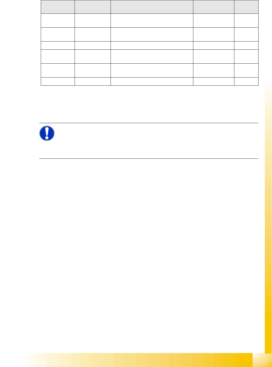
6-6: Travel ranges for X and Y axes (D4 and X4 shown as example)
The end of the X-axis travel range (software
end position) is 0.5 mm before the hardware end
position, which is 1.5 mm before the bumper. A
safety distance of 2.0 mm to the bumper is
adequate, if the X-axis moves into this area with
excessive speed.
The end of the Y-axis travel range (software
end position) is 1.5 mm before the hardware end
position. The Y-axis travel range for a particular
placement area is monitored in one direction by
the software end position and a bumper. In the
other direction, the travel range is calculated from
the position of the opposite gantry. A mutual
gantry-gantry position query is issued, which
regulates the start of the Y axes. The
communication exchange is via the SPI bus (Small
Processor Interface bus) between the Y axes and
reports their positions and speed (see description
of anti-crash function). The safety distance
between the gantry bumpers is 4 mm during
placement.
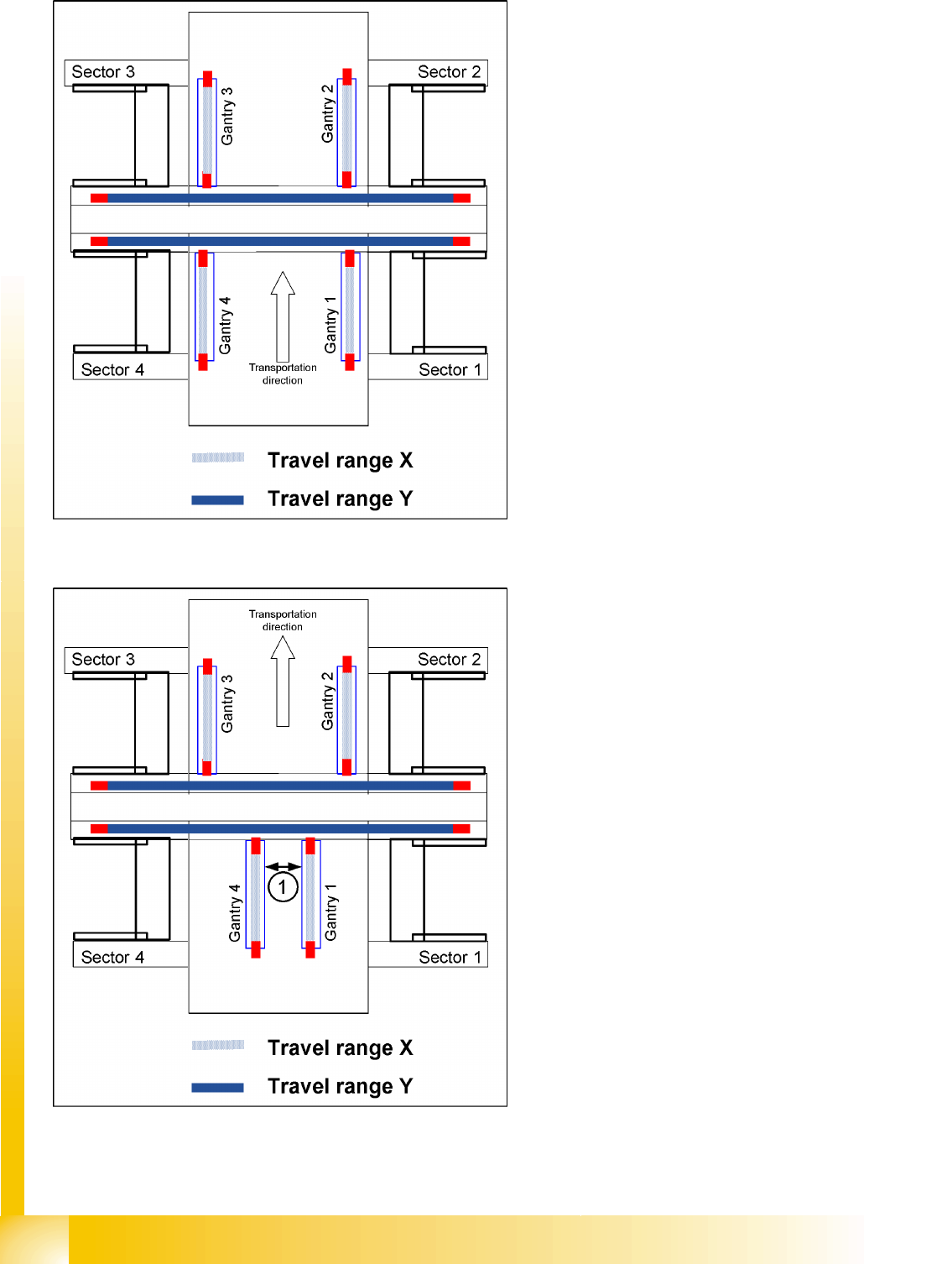
6-7: Travel ranges and safety distances for gantry axes (D4 and X4 shown
as example)
1. This means that, during travel range
calibration, the X-axis moves as far as
possible towards the minimum or maximum
position, until it touches the bumper.
The travel ranges are calculated, taking into
account the relevant safety distance.
2. In placement areas 1 and 2 of the D4, gantry
1/2 moves to the minimum position and gantry
4/3 to the maximum position, for calculation of
the Y-axis travel range.
3. The safety distance (1) between the sides of
the gantry facing each other is at least 4mm,
during placement.