JO-109-002_JG-0209.pdf - 第168页
5-A JO-109 1005-001 Section 5 Supplement • T roubleshooting against Main Errors • Others • Layout • Electrical Circuit Diagram Section 1 Scopee
4-79
JO-109
1005-001
4. Default Setting of Program for Feeder Measurement
¡
: Measurement Possible with Feeder Adjusting Jig
r
: The data measured by the height gauge can be transferred to the
feeder adjusting jig.
×
: Measurement Impossible
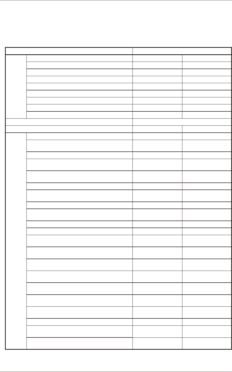
Table D38
Feeder Models
SL44040
Offset
Name
Lane #1 Origin Offset
○ ○
Lane #2 Origin Offset
○ ○
Lane #1 Offset X
○ ○
Lane #1 Offset Y
○ ○
Lane #1 Offset Z
△ △
Lane #2 Offset X
○ ○
Lane #2 Offset Y
○ ○
Lane #2 Offset Z
△ △
Sprocket Offset
× ○
Required Master Tape Models
JG-0009-22
Program Nos. (Initial Setting Mode)
129 130
Item
Type Name
SL44040-4X1_ORG/XY SL44040-4X1_SPROCKET
Type Name Type ID Nos.
(1 to N)
1 1
Inspection Type Nos. (1 to 5)
5 4
# of Sprocket Feeding Times
(1 to 100)
90 90
Sprocket Feeding Interval
(1 to 100)
9 2
Sprocket Feeding Delay (ms)
0 0
# of Components per
Sprocket Circle
90 90
Component Pitch (mm)
2.000 2.000
Lot Data Input Omission
Flag (0 or 1)
1 1
Fiducial Mark Position X
-3.650 -3.650
Fiducial Mark Position Y
-13.000 -13.000
Sprocket Feed Basic
Pitch Y
2.000 2.000
# of Divided Pulses for
Origin Offset Adjustment
256 256
# of Measured Pickup
Holes (1 or 2)
2 2
Measured Pickup Hole
Position #1 X
1.700 1.700
Measured Pickup Hole
Position #1 Y
0.000 0.000
Measured Pickup Hole
Position #2 X
11.200 11.200
Measured Pickup Hole
Position #2 Y
0.000 0.000
Feeder parameter le
(Before measurement)
SL44040-00005A.fdr SL44040-00004A.fdr
Feeder parameter le
(After measurement)
SL44040-00005B.fdr SL44040-00004B.fdr

5-A
JO-109
1005-001
Section 5
Supplement
•
Troubleshooting against Main Errors
•
Others
•
Layout
•
Electrical Circuit Diagram
Section 1 Scopee

5-B
JO-109
1005-001