JO-109-002_JG-0209.pdf - 第39页
2-3 JO-109 1.1 Procedures for Attachment of Camera Unit and Detachment of Fixtures 1005-001 (2) Push the side face of the camera assembly against the pilot pin on the X/Y stage and the pilot pin on the camera assembly bo…
2-2
JO-109
1.1 Procedures for Attachment of Camera Unit and Detachment of Fixtures
1005-001
1.1 Procedures for Attachment of Camera Unit and
Detachment of Fixtures
1.1.1 Required Tools
•
Hex-Head Wrenches for M3 and M4
•
Cutting Nipper
1.1.2 Procedure for Attachment of Camera Unit
Procedure
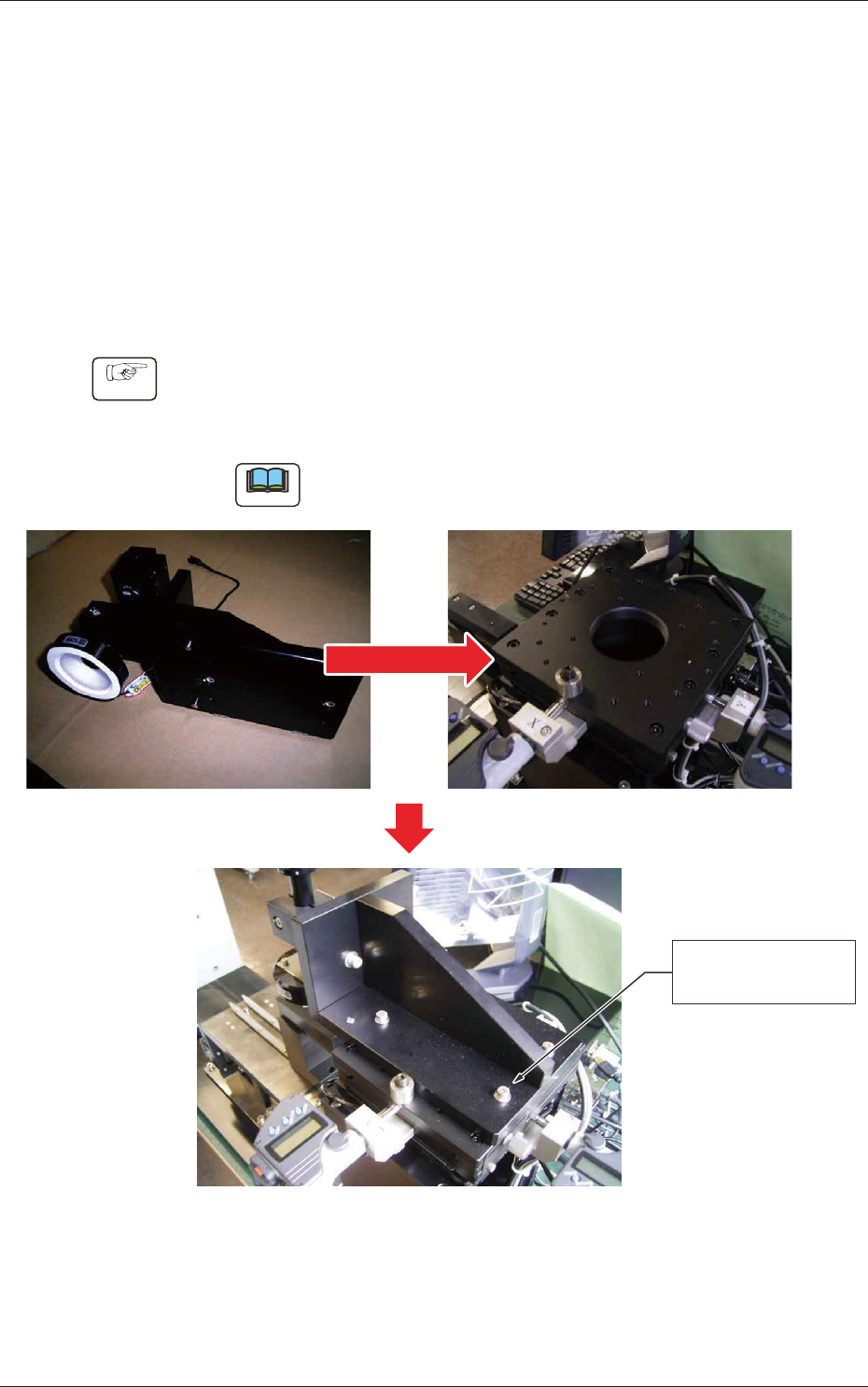
(1) Place the camera unit on the X/Y stage of the jig body and
temporarily x it on the X/Y stage with four bolts (SW + FW)
having M4L20 hexagonal recessed sockets (accessory parts).
Note
Before assembling it on the X/Y stage, make sure that there is
no dust and dirt on the mounting surface.
4-M4L20 (SW + FW)
Temporary Fixing
Fig. B2
2-3
JO-109
1.1 Procedures for Attachment of Camera Unit and Detachment of Fixtures
1005-001
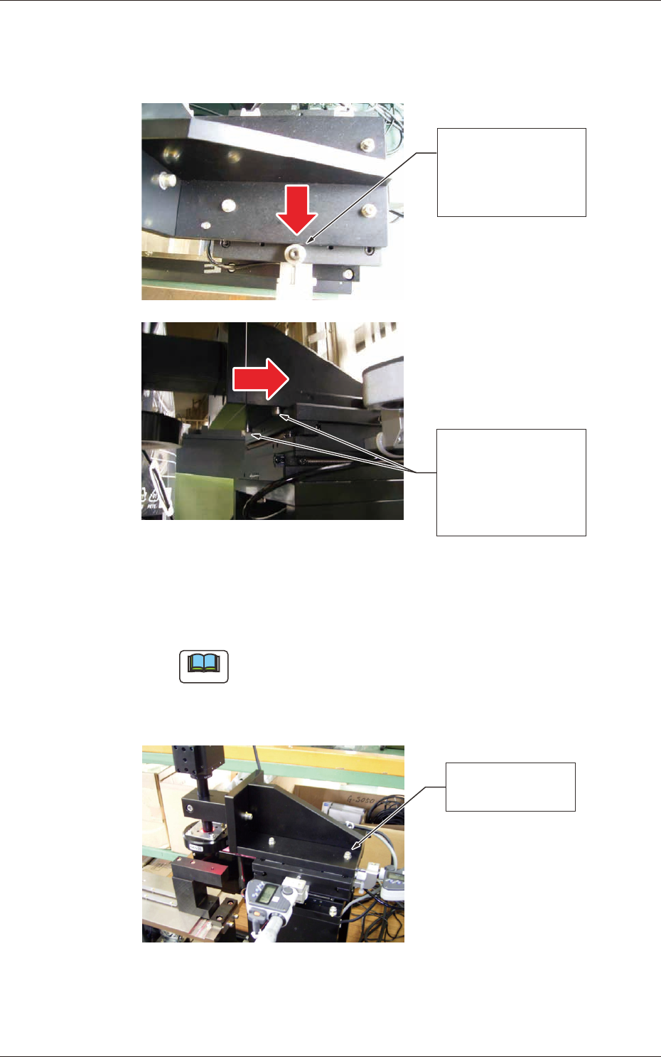
(2) Push the side face of the camera assembly against the pilot pin on
the X/Y stage and the pilot pin on the camera assembly bottom
against the side face of the X/Y stage for rm mounting.
Push the side face of
the camera assembly
against the pilot pin
on the X/Y stage.
Push the pilot pin of
the camera assembly
bottom against the
side face of the X/Y
stage.
Fig. B3
(3) After positioning, rmly tighten the four nuts (M4L20).
Tightening Torque: 3.00 to 3.66 N
•
m (30.6 to 37.4 kgf•cm)
Note
After tightening the nuts, make sure that there is no clearance
between the pin and the pushed (mating) surface.
When a clearance is left, follow the above-described steps
again, starting with Step (2).
Firm Tightening of
Four Nuts (M4L20)
Fig. B4
2-4
JO-109
1.1 Procedures for Attachment of Camera Unit and Detachment of Fixtures
1005-001
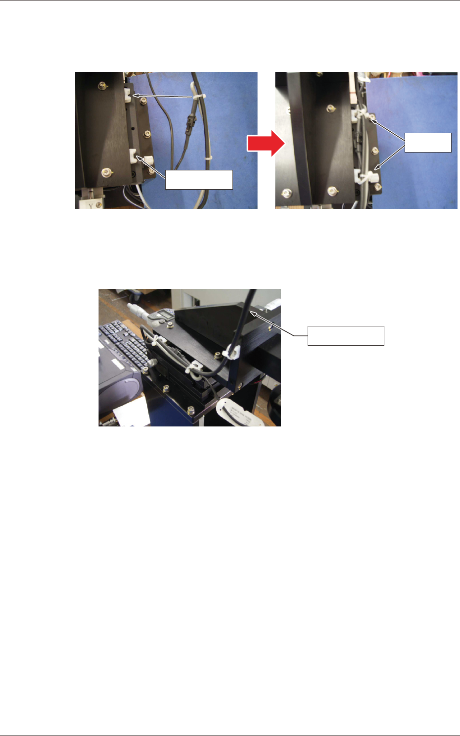
(4) Fasten the cables with tie wraps.
Adjust the tie wraps to the location of the tie mounts and x them
on the tie mounts after tightening the cable ties.
Tie Mount
Bundle
Fig. B5
The cameral cable should also be bundled and xed on the tie
mounts using the tie wraps.
Camera Cable
Fig. B6