JO-109-002_JG-0209.pdf - 第83页
3-31 JO-109 6.2 Chart 6.2.4 Polar Chart for Plane Errors The two-dimensional chart indicates the X and Y inspection values connected in the order of inspection. Y ellow Line : Inspected V alues Light Blue Line : X Axis L…
3-30
JO-109
6.2 Chart
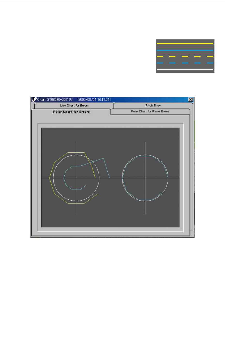
6.2.3 Polar Chart for Errors
The polar chart indicates the results of inspection performed at the
angular position of the sprocket.
Yellow Line
: X Values
Light Blue Line
: Y Values
Yellow Dashed Line
: X 0 Value
Light Blue Dashed Line
: Y 0 Value
White Solid Line
: CENTER Values
The errors in Lane #1 are displayed on the left side and the errors in Lane
#2 on the right side.
Fig. C24
1005-001
3-31
JO-109
6.2 Chart
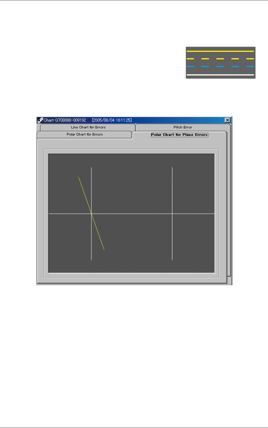
6.2.4 Polar Chart for Plane Errors
The two-dimensional chart indicates the X and Y inspection values
connected in the order of inspection.
Yellow Line
: Inspected Values
Light Blue Line
: X Axis
Light Blue Dashed Line
: Y Axis
White Solid Line
: CENTER Values
The intersection of Y and X axes is (0,0).
The errors in Lane #1 are displayed on the left side and the errors in Lane
#2 on the right side.
Fig. C25
1005-001
3-32
JO-109
1005-001
7. "Errors" Window
7. "Errors" Window
When an error occurs in a mechanical area or on the program, the contents
are displayed, prompting you to take some countermeasures against it.
When the [Error] button is pressed in each window, this window opens.
Normal Condition (No Error)
Error Occurrence
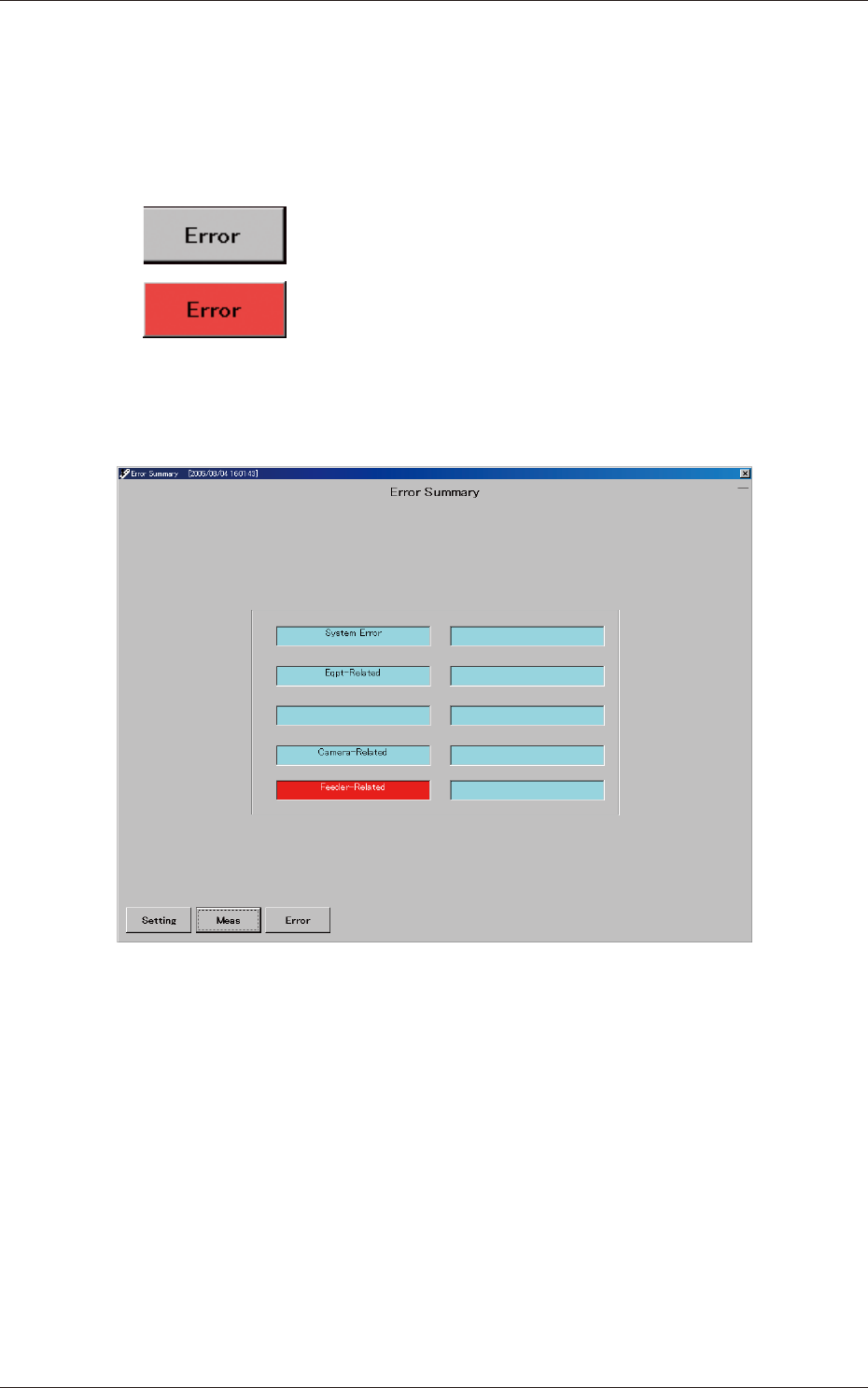
7.1 "Error Summary" Window
This window shows where errors have occurred.
Fig. C26 "Error Summary" Window
•
System Error
This is turned on when an error has occurred in an operating system or
internal state of the personal computer or in processing with its peripheral
equipment.
•
Eqpt-Related
This is turned on when an error has occurred in an mechanical area all
over the main machine.
•
Camera-Related
•
Feeder-Related
When you press the [Error] button again or the displayed area of the
summary in this window, the "Errors" window opens.