0197787-01_UM_HeadVerification_708_EN.pdf - 第76页
SIPLACE Head V erification User Manual Edition 01/2015 76 4.14.4 Mea ning of the Results Calibration value error at all segm ents: 1. Component sensor f itted at a slant Readjust c omponent sens or 2. Component sensor …
SIPLACE Head Verification
User Manual Edition 01/2015
75
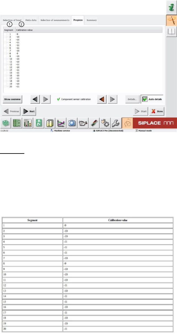
4.14.2 Explanation of Measurement Results in "Progress" Menu
After completion of the measurement, the following results appear in the "Progress2 menu:
Figure 52: Component sensor calibration result
Legend:
1. Segment measured
2. The Calibration value is calculated from the change in Z axis travel path during axis
overlapping (star axis - Z axis) and triggering of the component sensor.
4.14.3 Explanation of Measurement Results Using Results PDF
These results can be seen if you scroll down the "Summary" menu or generate a results PDF!
Figure 53: Results PDF component sensor calibration
See 6.14.2

SIPLACE Head Verification
User Manual Edition 01/2015
76
4.14.4 Meaning of the Results
Calibration value error at all segments:
1. Component sensor fitted at a slant Readjust component sensor
2. Component sensor lens defective Replace component sensor
3. Component sensor lens dirty Clean with isopropyl alcohol
4.15 "Segment Offset Up & Down" Measurement
The following tools are required for these measurements:
CPP: 12x nozzle type 2057 03070280-01 (calibration nozzle)
CP20P: 20x nozzle type 4235 03098748-01 (calibration nozzle)
CP20A: 20x nozzle type 1235 03015222-01 (calibration nozzle)
1x calibration component CPP 03010565-01
or
1x calibration component C&P20A/P 03034148-01
4.15.1 Explanation of Measurement – Procedure
The "Segment offset up & down" measurement checks the degree to which a segment is outside its
rotation axis. This eccentricity is known as the segment offset. The "segment offset up" describes the
rotation (offset) of the segment in docked state, meaning with the Z axis up. The "segment offset
down" describes the rotation of the segment in the bottom position. This position then illustrates the
eccentricity of the segment axis in the pickup or placement position, meaning the offset between the
component and PCB camera. This measurement is important and enables the machine to calculate
this displacement into the target positions during pickup and placement, thereby increasing the pickup
or placement accuracy.The "Segment offset up & down" measurement is performed for each segment,
in the top or bottom position and at four angles (0°, 90°, 180° and 270°), so that the exact rotation can
be determined and also so that the influence of the Z linear guide between the segment top and
segment bottom positions can be calculated into the equation.
The results of these measurements provide feedback about the following sources of errors:
1. Deformed segments
2. Defective Z linear guides of DP/segments
Measurement steps:
1. Firstly, the exact position of the calibration component in the bag is determined with the PCB
camera, as the actual position (the exact center and position), and is then adopted as the
pickup position. This center is determined using 4 points at the corners of the calibration
component.
2. Segment 1 now moves downwards at an angle of 0° and picks the calibration component up
from the pickup position determined (calibration component center).
3. Segment 1 is moved upwards again.
4. Segment 1 is rotated by the star over the component camera.
5. The component camera measures the four calibration component structure fiducials to
determine the exact position of the calibration component to the camera center, thereby
optically centering the calibration component.The offset values determined here are saved as
Up X [µm] and Up Y [µm]. This value now describes the eccentricity of the calibration
component to the camera center.This value provides the "Segment offset up" for segment 1 at
0°, as we can assume that segment 1 picked up the calibration component exactly in the
center.
The offset values determined are calculated into the following placement (putdown) of the
calibration component (calibration component bag) as correction values.
6. The star now rotates the segment with the calibration component back into the placement
position.
SIPLACE Head Verification
User Manual Edition 01/2015
77
7. Segment 1 and the Z axis are moved downwards and the calibration component is placed in
the bag at an angle of 0° (DP/segment angle) and with the corrected offset values Up X [µm]
and Up Y [µm], as a placement position.
8. The PCB camera now moves over the calibration component and once more determines the
four points in the calibration component corners, to find the exact position of the calibration
component in the bag. This provides the offset values Down X [µm] and Down Y [µm], which
describe the eccentricity of the calibration component to the PCB camera center. This value
describes exactly the offset of the segment 1 center at a placement angle of 0°, when
segment 1 is in the placement position. This provides the exact displacement of segment 1 at
a placement angle of 0°, describing how much the Z linear guide has changed the segment
position at the top to the segment position at the bottom.This deviation also describes the
offset of the component camera to the PCB camera for this segment.
9. The calibration component position determined is now used again as actual pickup position for
the following measurement.
10. Segment 1 now picks up at 90°.
11. Segment 1 is moved upwards and can be rotated under the component camera with the help
of the star.
12. The component camera measures the four calibration component structure fiducials to
determine the exact position of the calibration component to the camera center.The offset
values determined here are saved as Up X [µm] and Up Y [µm]. This value now describes
the eccentricity of the calibration component to the camera center.This value provides the
"Segment offset up" for segment 1 at 90°, as we can assume that segment 1 picked up the
calibration component exactly in the center.
13. The star now rotates the segment with the calibration component back into the placement
position.
14. Segment 1 and the Z axis are moved downwards and the calibration component is placed in
the bag at an angle of 90° (DP/segment angle) and with the corrected offset values Up X [µm]
and Up Y [µm], as a placement position.
15. The PCB camera now moves over the calibration component and once more determines the
four points in the calibration component corners, to find the exact position of the calibration
component in the bag. This provides the offset values Down X [µm] and Down Y [µm], which
describe the eccentricity of the calibration component to the PCB camera center. This value
describes exactly the offset of the segment 1 center at a placement angle of 90°, when
segment 1 is in the placement position. This provides the exact displacement of segment 1 at
a placement angle of 90°, describing how much the Z linear guide has changed the segment
position at the top to the segment position at the bottom. This deviation also describes the
offset of the component camera to the PCB camera for this segment.
16. The calibration component position determined is now used again as actual pickup position for
the following measurement.
17. The measurement steps are now repeated for segment 1 with the DP angles 180° and 270°
18. The values determined for segment 1 Down X [µm] and Down Y [µm] are taken as an
absolute 0 for all other calculations of all segment offsets. The "Segment offset down" for
segment 1 is the reference value as all other offsets for all other segments refer to this initial
value.
19. All measurement steps are now performed for the other segments at the angles 0°, 90°, 180°
and 270°.
20. The calibration component stays in its position at 0° for the entire measurement and does not
change its angle!The measured angles refer to the angles of the DP at which the calibration
component is picked up from the DP.
4.15.2 Explanation of Measurement Results in "Progress" Menu
After completion of the measurement, the following results appear in the "Progress" menu: