0197787-01_UM_HeadVerification_708_EN.pdf - 第13页
SIPLACE Head V erification User Manual Edition 01/2015 13 2.2.6 End of Measurement – Summary Figure 6: End o f measureme nt – Summ ary Once all meas urements have been c ompleted, the s ystem will automatically sw itch o…
SIPLACE Head Verification
User Manual Edition 01/2015
12
2.2.5 During Measurements - Progress
After clicking the "Start" button, the machine automatically switches over to measurement mode and
works through the "Selection of Measurements" (chapter 4.2.3) specified.
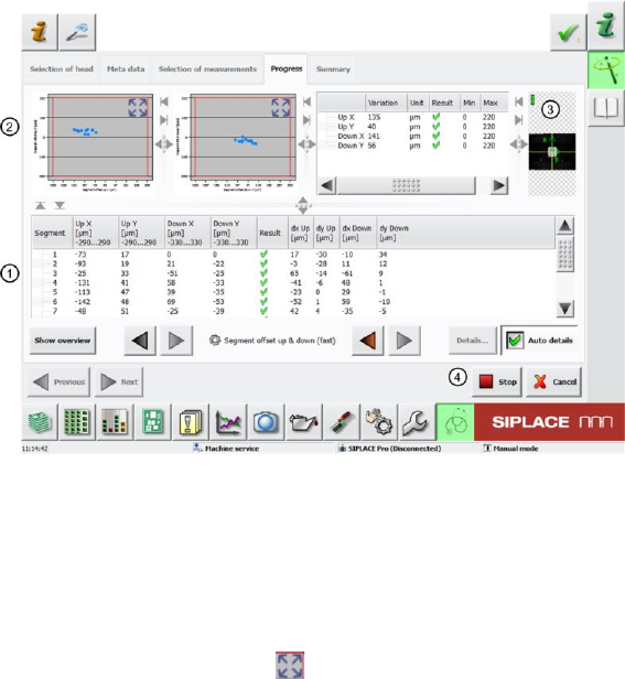
The following example shows the GUI during the measurement.
Figure 5: During the measurement
The screen (1) shows the segment being measured and the results of the partial measurements. You
can also see whether the measurement for this segment was successful (OK green tick / NOK
red X).
The diagrams (2) show the results of the individual partial measurements.
Select the extraction button to zoom in on the diagram. The diagram bar shows the measurement
values depicted.
If an image is captured with the camera (PCB or component) during measurement, a live image will be
displayed (3).This is not the case in each measurement!
If you want to interrupt or terminate the measurement, use the "Stop" button (4).
The measurement will not stop immediately as the sequence currently running for a segment will be
finished first.
After the procedure has been stopped, click "Continue" to start the process again. The partial
measurement will start again at the beginning and will not just continue from the place at which it was
stopped.
In the event of an emergency stop, click on the "Stop" button and/or the emergency STOP button. The
"Stop" button alone is too slow!
SIPLACE Head Verification
User Manual Edition 01/2015
13
2.2.6 End of Measurement – Summary
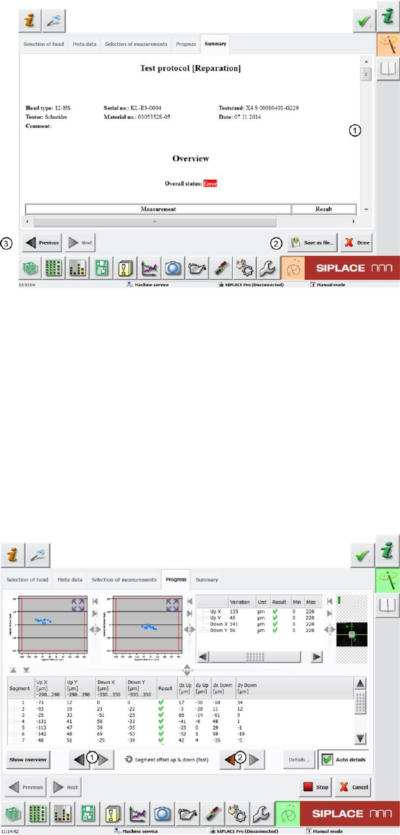
Figure 6: End of measurement – Summary
Once all measurements have been completed, the system will automatically switch over to the
"Summary" menu and the results log (1) appears displaying all data relevant for the head.
You can also view an "Overall Status".
An "Error" is shown if a measurement or just a part of it couldn’t be finished successfully.
The whole measurement log can be saved as a PDF by the "Save as File" (2) button after selecting
the storage location.
Click the "Done" button to delete the results. If the results have not been saved as a PDF, they will be
lost and you will need to repeat the measurement.
The "Previous" (3) button takes you back to the previous menu: "Progress".
This menu shows a detailed view of the individual measuring results, as described at 4.2.5.
Figure 7: Scroll through results
Once you are back in the "Progress" menu, you can use the arrow keys (1) to navigate between the
individual measurements.
Use the red arrow (2) to navigate directly to the measurements which have an error.
If the whole measurement was completed with no errors, these red arrows will remain disabled.

SIPLACE Head Verification
User Manual Edition 01/2015
14
3 Prerequisites for Head Verification
3.1 Preparatory Tasks
If head verification is performed systematically in your production environment, we recommend that
you prepare complete magazines with the required nozzle types. This reduces the conversion time for
the NC.
3.2 Vacuum Pump Mode
This applies primarily to heads of type CP20P, as these heads function with a vacuum pump as a
default.
3.3 Disabled Segments
Note about disabled segments (disabled/not in use):
If segments have been disabled, the head verification will also omit these segments.The
measurements will not be performed at these segments.
However, an error will occur for each measurement (red cross), since there are measurements
missing.
Segment 1 may not be disabled, as this is required for the general functioning of the head.
The other segments may contain disabled segments (disabled/not in use).
Attention:
The following needs to be taken into consideration for machines which are in a placement area
equipped with a vacuum pump.
As the vacuum is generated with a vacuum pump and no longer at the head, for the complete
placement area, any openings in the closed vacuum pump system will have a negative influence on
the vacuum values.
We recommend for all machines equipped with a vacuum pump, that the other gantry in the
placement area, at which no head verification is to be performed, has the following nozzle
configuration:
Closed red vacuum nozzles (vacuum system closed optimum solution)
Nozzles with small cross-section, e.g. 4104 oder 4105 (small opening through nozzle cross
section influence on vacuum system acceptable)
This means that you may need to double the amount of closed red nozzles.