0197787-01_UM_HeadVerification_708_EN.pdf - 第15页
SIPLACE Head V erification User Manual Edition 01/2015 15 3.4 Overvie w of Measurements fo r CPP (20 m in) The following tools are r equired for m easur ements: 12x nozz le type 20 57 03070280- 01 (calibration nozzle) 12…

SIPLACE Head Verification
User Manual Edition 01/2015
14
3 Prerequisites for Head Verification
3.1 Preparatory Tasks
If head verification is performed systematically in your production environment, we recommend that
you prepare complete magazines with the required nozzle types. This reduces the conversion time for
the NC.
3.2 Vacuum Pump Mode
This applies primarily to heads of type CP20P, as these heads function with a vacuum pump as a
default.
3.3 Disabled Segments
Note about disabled segments (disabled/not in use):
If segments have been disabled, the head verification will also omit these segments.The
measurements will not be performed at these segments.
However, an error will occur for each measurement (red cross), since there are measurements
missing.
Segment 1 may not be disabled, as this is required for the general functioning of the head.
The other segments may contain disabled segments (disabled/not in use).
Attention:
The following needs to be taken into consideration for machines which are in a placement area
equipped with a vacuum pump.
As the vacuum is generated with a vacuum pump and no longer at the head, for the complete
placement area, any openings in the closed vacuum pump system will have a negative influence on
the vacuum values.
We recommend for all machines equipped with a vacuum pump, that the other gantry in the
placement area, at which no head verification is to be performed, has the following nozzle
configuration:
Closed red vacuum nozzles (vacuum system closed optimum solution)
Nozzles with small cross-section, e.g. 4104 oder 4105 (small opening through nozzle cross
section influence on vacuum system acceptable)
This means that you may need to double the amount of closed red nozzles.
SIPLACE Head Verification
User Manual Edition 01/2015
15
3.4 Overview of Measurements for CPP (20 min)
The following tools are required for measurements:
12x nozzle type 2057 03070280-01 (calibration nozzle)
12x nozzle type 2069 03094135-01 (vacuum nozzle red, closed)
2x magazine for 2xxx nozzle 03066107-01
1x calibration tool CPP 03010565-01 (placed in machine)
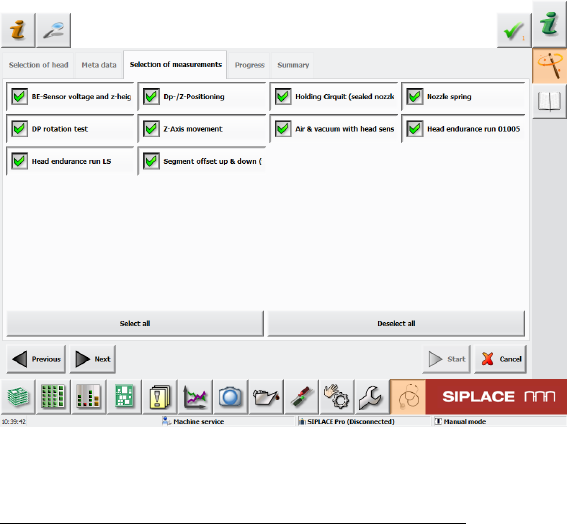
Figure 8: Overview measurements CPP
The following measurements are performed in order:
1. Component sensor voltage and z-heights chapter 6.1 (00:46 min)
2. DP/Z positioning chapter 6.11 (00:56 min)
3. Holding circuit (sealed nozzle) chapter 6.2 (00:06 min)
4. Nozzle spring chapter 6.3 (01:09 min)
5. DP rotation test chapter 6.12 (01:57 min)
6. Z-axis movement chapter 6.4 (05:30 min)
7. Air & vacuum with head sensors chapter 6.6 (01:15 min)
8. Head endurance run 01005 chapter 6.7 (03:05 min)
9. Head endurance run LS chapter 6.8 (02:37 min)
10. Segment offset up & down (fast) chapter 6.9 (02:17 min)
The specified times may deviate and are only for guidance purposes. If the measurements are
performed as single measurements (not in "Select all" mode), longer script loading times (approx. 1
min) could delay the single measurement!
SIPLACE Head Verification
User Manual Edition 01/2015
16
3.5 Overview of Measurements for CP20P
3.5.1 SW708.x up to Image 126 (45 Min)
The following tools are required for measurements:
20x nozzle type 4235 03098748-01 (calibration nozzle)
20x nozzle type 4069 03106244-01 (vacuum nozzle red, closed)
20x nozzle type 4004 03098544-01
20x nozzle type 4105 03102457-01
4x magazine for 4xxx nozzle 03101503-01
1x calibration tool C&P20A/P 03034148-01 (placed in machine)
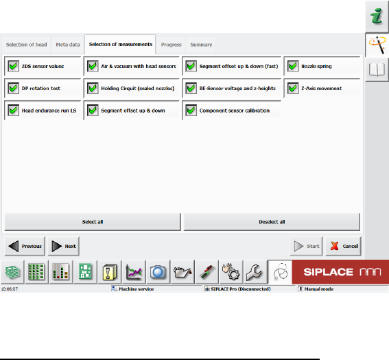
Figure 9: Overview measurements for CP20P to image 126
The following measurements are performed in order:
1. ZDS sensor values chapter 6.13 (07:26 min)
2. Air & vacuum with head sensors chapter 6.6 (02:09 min)
3. Segment offset up & down (fast) chapter 6.9 (02:32 min)
4. Nozzle spring chapter 6.3 (01:38 min)
5. DP rotation test chapter 6.12 (02:59 min)
6. Holding circuit (sealed nozzle) chapter 6.2 (01:35 min)
7. Component sensor voltage and z-heights chapter 6.1 (01:32 min)
8. Z-axis movement chapter 6.4 (04:36 min)
9. Head endurance run LS chapter 6.8 (02:27 min)
10. Segment offset up & down chapter 6.15 (10:25 min)
11. Component sensor calibration chapter 6.14 (09:13 min)
The specified times may deviate and are only for guidance purposes. If the measurements are
performed as single measurements (not in "Select all" mode), longer script loading times (approx. 1
min) could delay the single measurement!