0197787-01_UM_HeadVerification_708_EN.pdf - 第22页
SIPLACE Head V erification User Manual Edition 01/2015 22 1. Dirty component sensor lens (prism ) Clean with cleansing t ip and isoprop yl alcohol 2. "Component sensor voltage value" check in the head "S…
SIPLACE Head Verification
User Manual Edition 01/2015
21
4.1.3 Explanation of Measurement Results Using Results PDF
These results can be seen if you scroll down the "Summary" menu or generate a results PDF!
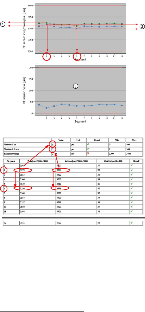
Figure 13: Results PDF for component sensor diagram
Figure 14: Component sensor table results
The "Variation Z-up" (1) value is calculated from the lowest "Z-up" value for segment 6 and the highest
"Z-up" value for segment 2! -> 3572µm – 3530µm = 42µm (1)
The "Variation Z-down" (2) value is calculated from the lowest "Z-down" value for segment 6 and the
highest "Z-down" value for segment 2! -> 3549µm – 3498µm = 51µm (2)
The hysteresis values for each segment "Z-delta" are calculated from the difference between "Z-up"
and "Z-down"! -> Segment 4 as example: 3546µm – 3507µm = 39µm (hysteresis)
4.1.4 Meaning of the Results
"Component sensor voltage" error
If the measured analog voltage value is under the plausible tolerance, the following causes and
measures apply:

SIPLACE Head Verification
User Manual Edition 01/2015
22
1. Dirty component sensor lens (prism)
Clean with cleansing tip and isopropyl alcohol
2. "Component sensor voltage value" check in the head "Single Functions"
If OK there, this error can be ignored here
3. Component sensor lens (prism) check for damage
To check the lens, hold a sheet of white paper between the transmitter and the receiver. A
red dot should be shown. If this is diffused, the lens is damaged.
Replace component sensor
4. Internal component sensor electronics defective
Replace component sensor
If the measured analog voltage value is above the plausible tolerance, the following causes apply:
5. Internal component sensor electronics defective
Replace component sensor
"Z-delta" / "Z-down" / "Z-up" error at all segments
1. The driver (jaws) of the Z axis has been displaced or moved
CPP: Replace front plate with Z motor assembly
CP20A: Replace Z axis assembly
CP20P: Replace Z unit assembly
CP20A: Readjust jaws (acc. to instructions)
2. Component sensor defective or dirty
Replace or clean the component sensor
"Z-delta" / "Z-down" / "Z-up" error at individual segments
1. Bad nozzle seat
Replace nozzle
Sight check, replace DP if necessary
2. Driver bearing on DP displaced
Replace the DP
3. Linear guide (segment guide) of DP displaced
CP20P/A: Replace the DP
CPP: Replace the segment guide
SIPLACE Head Verification
User Manual Edition 01/2015
23
4.2 "Holding Circuit (Sealed Nozzles)" Measurement
The following tools are required for these measurements:
CPP: 12x nozzle type 2069 03094135-01 (vacuum nozzle red, closed)
CP20P: 20x nozzle type 4069 03106244-01 (vacuum nozzle red, closed)
CP20A: 20x nozzle type 1069 03094112-01 (vacuum nozzle red, closed)
4.2.1 Explanation of Measurement – Procedure
Firstly, a star axis reference run is performed to bring the axis into a defined position.
Vacuum is then applied to the holding circuit, so that each segment is in the state it would be in if, after
pickup, there was a component on the nozzle.This can be simulated by using the closed vacuum
nozzle.
The vacuum value for the holding circuit is then measured for each segment.
The results of these measurements provide feedback about the following sources of errors:
1. Defective filter disks
2. Vacuum hoses defective or dirty
3. Vacuum pump defective
4. Vacuum pump loop leaky
5. Holding circuit dirty
6. Leaky vacuum nozzle
7. Bad nozzle seat
4.2.2 Explanation of Measurement Results in "Progress" Menu
After completion of the measurement, the following results appear in the "Progress" menu:
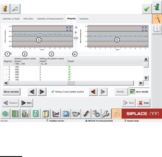
Figure 15: Holding circuit (sealed nozzles) – Progress menu
The results shown are from measuring the holding circuit of a CPP head. The screen will look slightly
different for a CP20P/A, although the result is the same!
Legend:
1. Segment measured
2. Measured holding circuit vacuum value at the segment with closed vacuum nozzle in mbar.
The Holding (sealed nozzle) value must be within a plausible tolerance (in this case -950..-
700mbar).