0197787-01_UM_HeadVerification_708_EN.pdf - 第25页
SIPLACE Head V erification User Manual Edition 01/2015 25 4.2.3 Explanation of Measurement Results Using Results PDF These results can b e seen if you scroll down the "Sum mary" menu or generat e a results PDF!…

SIPLACE Head Verification
User Manual Edition 01/2015
24
3. Holding circuit switched off, vacuum disabled. This measurement is used to check whether the
underpressure is reduced quickly, after the vacuum has been switched off. In an ideal case,
the pressure should be 0mbar (atmospheric pressure). The Holding off (sealed nozzle) value
must be within a plausible tolerance (in this case -10..10mbar).
This measurement is only performed for the CPP head.
This measurement is not performed for the CP20P/A and is therefore not shown in these
cases.
4. Results display (OK green tick / NOK red X)
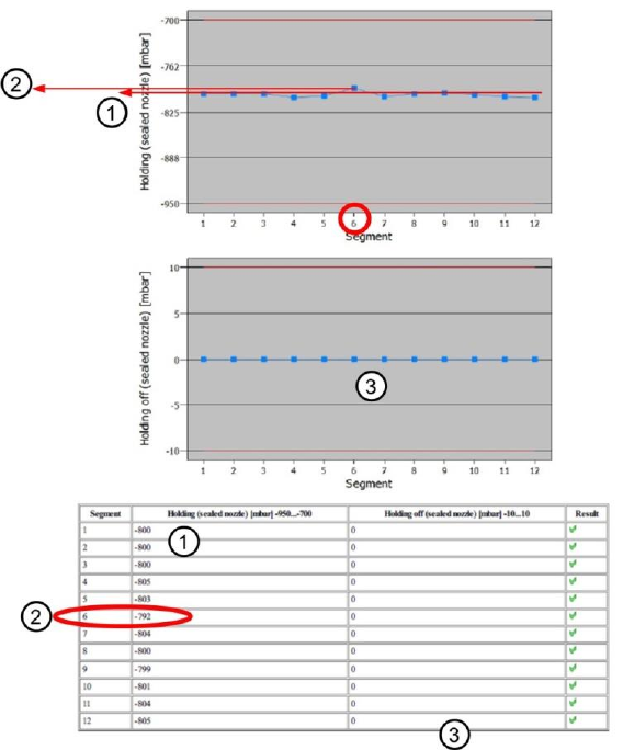
5. This diagram illustrates the "Holding (sealed nozzle)" values for the segments.
Blue line Holding (sealed nozzle) in mbar for the individual segments
Red border Min and max tolerances (in our case -950..-700mbar)
Use the button to zoom in on the diagram.
6. This diagram illustrates the "Holding off (sealed nozzle)" values for the segments.
Blue line Holding off (sealed nozzle) in mbar for the individual segments
Red border Min and max tolerances (in our case -10..10mbar)
Use the button to zoom in on the diagram.
This diagram is only available for the CPP.
This diagram will not be shown for the CP20P/A.
SIPLACE Head Verification
User Manual Edition 01/2015
25
4.2.3 Explanation of Measurement Results Using Results PDF
These results can be seen if you scroll down the "Summary" menu or generate a results PDF!
Figure 16: Results PDF for holding circuits
The measurement of the holding circuit vacuum for each segment has shown a relatively consistent
result so that we can assume that the vacuum system for this head is OK and does not have any
leaks.
The slight variation in the lower vacuum value at segment 6 (2) = -792mbar indicates that this value
deviates by approx.-8mbar from the expected vacuum-holding circuit average value of approx. -
800mbar (1). This could be due to a bad nozzle seat, a slightly leaky vacuum nozzle, a defective filter
disk or minor contamination of the holding circuit hose. However, the measurement in our example is
OK.
If you were to perform another measurement after a certain period and would discover a higher
deviation from the average value, this would indicate a trend and the probability that this segment will
sooner or later have a problem with the holding circuit.
Diagram (3) illustrates again the measurement of the absolute pressure after release of the vacuum, to
confirm the correct changeover to air blast.

SIPLACE Head Verification
User Manual Edition 01/2015
26
4.2.4 Meaning of the Results
"Holding (sealed nozzles)" error at all segments:
1. Vacuum pump defective (in which case the other head in the placement area should have the
same problems!)
Check hoses
Perform vacuum pump service (this error is only possible for CP20P/A, as CPP is not
designed for vacuum pump operation)
2. CP20P/A heads are not converted for vacuum pump mode and are therefore leaky
Retrofit CP20P/A for vacuum pump mode according to conversion instructions (this error is
only possible with CP20P/A, as the CPP is not designed for vacuum pump operation)
3. O-ring between vacuum unit and silencer is leaky
Check the O-ring assembly or replace it
4. Seal (four-hole rubber disk) for holding circuit incorrectly fitted or damaged
Check the seal position or replace it
"Holding (sealed nozzles)" error at individual segments:
1. Filter disk is damaged or incorrectly fitted
Replace filter disk with new one
2. Vacuum hose for segment damaged or dirty
Clean or replace the vacuum hose
3. Holding circuit unit dirty
Clean the holding circuit unit in ultrasound bath
4. Leaky vacuum nozzle
Replace the vacuum nozzle
"Holding (sealed nozzles)" error at several segments:
1. Holding circuit unit dirty
Clean the holding circuit unit in ultrasound bath
2. Seal (four-hole rubber disk) for holding circuit incorrectly fitted or damaged
Check the seal position or replace it
4.3 "Nozzle Spring" Measurement
The following tools are required for these measurements:
CPP: 12x nozzle type 2069 03094135-01 (vacuum nozzle red, closed)
CP20P: 20x nozzle type 4004 03098544-01 (will be replaced with 4069)
CP20A: 20x nozzle type 1069 03094112-01 (vacuum nozzle red, closed)
4.3.1 Explanation of Measurement – Procedure
This measurement is used to check the segment spring. The values determined indicate the state of
the spring in reference to its deflection, brittleness in general and how the switching (signal) threshold
is at the Z axis light barrier.
The results of these measurements provide feedback about the following sources of errors:
1. The functionality of the Z-down light barrier (CP20P/A 1x on head / CPP12x each
segment)
2. State of segment spring
3. State of cover switching rings (CP20A only)