0197787-01_UM_HeadVerification_708_EN.pdf - 第27页
SIPLACE Head V erification User Manual Edition 01/2015 27 Measurement steps: 1. Firstly, the entire hea d is referenced and th e vacuum no zzles at the no zzle station are press ed onto the DP to ensure a f irm seat. 2. …

SIPLACE Head Verification
User Manual Edition 01/2015
26
4.2.4 Meaning of the Results
"Holding (sealed nozzles)" error at all segments:
1. Vacuum pump defective (in which case the other head in the placement area should have the
same problems!)
Check hoses
Perform vacuum pump service (this error is only possible for CP20P/A, as CPP is not
designed for vacuum pump operation)
2. CP20P/A heads are not converted for vacuum pump mode and are therefore leaky
Retrofit CP20P/A for vacuum pump mode according to conversion instructions (this error is
only possible with CP20P/A, as the CPP is not designed for vacuum pump operation)
3. O-ring between vacuum unit and silencer is leaky
Check the O-ring assembly or replace it
4. Seal (four-hole rubber disk) for holding circuit incorrectly fitted or damaged
Check the seal position or replace it
"Holding (sealed nozzles)" error at individual segments:
1. Filter disk is damaged or incorrectly fitted
Replace filter disk with new one
2. Vacuum hose for segment damaged or dirty
Clean or replace the vacuum hose
3. Holding circuit unit dirty
Clean the holding circuit unit in ultrasound bath
4. Leaky vacuum nozzle
Replace the vacuum nozzle
"Holding (sealed nozzles)" error at several segments:
1. Holding circuit unit dirty
Clean the holding circuit unit in ultrasound bath
2. Seal (four-hole rubber disk) for holding circuit incorrectly fitted or damaged
Check the seal position or replace it
4.3 "Nozzle Spring" Measurement
The following tools are required for these measurements:
CPP: 12x nozzle type 2069 03094135-01 (vacuum nozzle red, closed)
CP20P: 20x nozzle type 4004 03098544-01 (will be replaced with 4069)
CP20A: 20x nozzle type 1069 03094112-01 (vacuum nozzle red, closed)
4.3.1 Explanation of Measurement – Procedure
This measurement is used to check the segment spring. The values determined indicate the state of
the spring in reference to its deflection, brittleness in general and how the switching (signal) threshold
is at the Z axis light barrier.
The results of these measurements provide feedback about the following sources of errors:
1. The functionality of the Z-down light barrier (CP20P/A 1x on head / CPP12x each
segment)
2. State of segment spring
3. State of cover switching rings (CP20A only)

SIPLACE Head Verification
User Manual Edition 01/2015
27
Measurement steps:
1. Firstly, the entire head is referenced and the vacuum nozzles at the nozzle station are pressed
onto the DP to ensure a firm seat.
2. The gantry then moves over the conveyor side.
3. Segment 1 is rotated into the placement position.
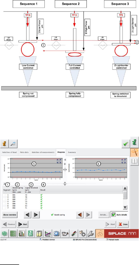
4. Sequence 1
The Z axis moves the segment to the conveyor side with the travel profile TP18 [TP18 DOWN
PICK CALIBRATE]. This travel profile constantly monitors the current value of the Z motor.As
soon as this rises, an end position signal is issued.This ensures that the minimum force at the
tip of the nozzle (lowest placement force approx. 1N) works. This also means that, in this
case, the segment spring is not yet deformed. The Z axis position for the travel path is
therefore determined here without spring deflection.
The value determined is Z-Low Force [µm].
5. The Z axis then moves back up again using travel profile TP1 [TP1 ABSOLUT DEFAULT].
6. Sequence 2
Immediately afterwards, the Z axis position at maximum spring deflection (when the spring is
fully compressed) is determined for segment 1 alone. For this, the Z axis is moved downwards
using the travel profile TP13 [TP13 NOZZLE CHANGER DOWN]. This travel profile is also
used during nozzle changeover, as the nozzle needs to be pressed fully into the nozzle
garage!
The Z axis therefore moves the nozzle to the conveyor side. The travel profile ensures that the
Z axis is moved as far down as possible, until the Z motor current reaches the value defined in
the machine data (or eSW), which corresponds to a maximum contact force which does not
damage the axis mechanics or the printed circuit board.
The Z axis moves with the nozzle tip to the conveyor side and fully compresses the segment
spring.
The value determined is Z-High Force [µm].
7. The Z axis then moves back up again using travel profile TP1 [TP1 ABSOLUT DEFAULT].
8. Sequence 3
Directly afterwards, segment 1 is moved downwards using travel profile TP2 [TP2 DOWN
PICK LIGHTBARRIER]. This travel profile helps check the Z axis position at which the Z-down
light barrier is triggered.
The Z axis is moved downwards. Shortly after leaving the top position, the Z-down light barrier
is switched.As soon as the nozzle touches the conveyor edge, the segment spring is
compressed. The Z axis continues to travel until the segment spring is compressed enough for
the switching ring on it to trigger the light barrier. The signal emitted marks the end position.
The value determined is Z-Light Barrier [µm].
This value stands for "normal" placement with no special runs, the force is approx. 1.8N – 2N,
or in accordance with the spring fitted in the segment.
9. The system now calculated the value for the complete deflection of the segment spring Nozzle
Spring Value [µm] . (1)
This is calculated by finding the difference between the Z axis position at minimum force (no
deflection) and maximum force (complete compression of the spring)
Nozzle Spring [µm] = Z-High Force [µm] – Z-Low Force [µm]
10. The system now calculates how far the segment spring needs to be compressed before the
light barrier Z-down triggers.
This value is known as the Signal Threshold (2).
This is calculated by finding the difference between the Z axis position at minimum force (no
deflection) and the Z axis position when the Z-down light barrier is triggered (breakaway
torque of spring).
Signal Threshold [µm] = Z-Light Barrier [µm] – Z-Low Force [µm]
11. The Z axis then moves back up again using travel profile TP1 [TP1 ABSOLUT DEFAULT].
12. The star then rotates by one segment.
SIPLACE Head Verification
User Manual Edition 01/2015
28
13. Steps 4 – 11 are performed for each of the other segments.
Figure 17: Nozzle spring function
4.3.2 Explanation of Measurement Results in "Progress" Menu
After completion of the measurement, the following results appear in the "Progress" menu:
Figure 18: Nozzle spring results
Legend:
1. Segment measured
2. Calculated value for complete spring deflection for segment.
This is calculated by finding the difference between the Z axis position at minimum force (no
deflection) and maximum force (complete compression of the spring)
Nozzle Spring [µm] = Z-High Force [µm] – Z-Low Force [µm]
3. Calculated value of signal threshold, which describes the breakaway torque of the spring.
This is calculated by finding the difference between the Z axis position at minimum force (no
deflection) and the Z axis position when the Z-down light barrier is triggered (breakaway
torque of spring).