0197787-01_UM_HeadVerification_708_EN.pdf - 第28页
SIPLACE Head V erification User Manual Edition 01/2015 28 13. Steps 4 – 11 ar e perform ed for each of the other s egments. Figure 17 : Nozz le spring function 4.3.2 Explanation of Measurement Results in "Progress&q…

SIPLACE Head Verification
User Manual Edition 01/2015
27
Measurement steps:
1. Firstly, the entire head is referenced and the vacuum nozzles at the nozzle station are pressed
onto the DP to ensure a firm seat.
2. The gantry then moves over the conveyor side.
3. Segment 1 is rotated into the placement position.
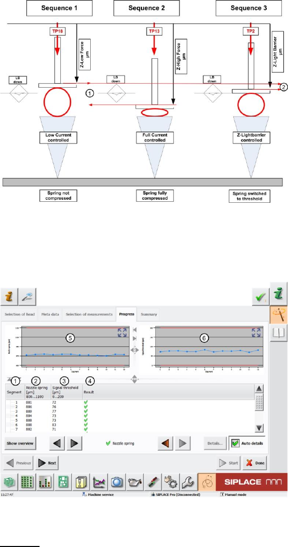
4. Sequence 1
The Z axis moves the segment to the conveyor side with the travel profile TP18 [TP18 DOWN
PICK CALIBRATE]. This travel profile constantly monitors the current value of the Z motor.As
soon as this rises, an end position signal is issued.This ensures that the minimum force at the
tip of the nozzle (lowest placement force approx. 1N) works. This also means that, in this
case, the segment spring is not yet deformed. The Z axis position for the travel path is
therefore determined here without spring deflection.
The value determined is Z-Low Force [µm].
5. The Z axis then moves back up again using travel profile TP1 [TP1 ABSOLUT DEFAULT].
6. Sequence 2
Immediately afterwards, the Z axis position at maximum spring deflection (when the spring is
fully compressed) is determined for segment 1 alone. For this, the Z axis is moved downwards
using the travel profile TP13 [TP13 NOZZLE CHANGER DOWN]. This travel profile is also
used during nozzle changeover, as the nozzle needs to be pressed fully into the nozzle
garage!
The Z axis therefore moves the nozzle to the conveyor side. The travel profile ensures that the
Z axis is moved as far down as possible, until the Z motor current reaches the value defined in
the machine data (or eSW), which corresponds to a maximum contact force which does not
damage the axis mechanics or the printed circuit board.
The Z axis moves with the nozzle tip to the conveyor side and fully compresses the segment
spring.
The value determined is Z-High Force [µm].
7. The Z axis then moves back up again using travel profile TP1 [TP1 ABSOLUT DEFAULT].
8. Sequence 3
Directly afterwards, segment 1 is moved downwards using travel profile TP2 [TP2 DOWN
PICK LIGHTBARRIER]. This travel profile helps check the Z axis position at which the Z-down
light barrier is triggered.
The Z axis is moved downwards. Shortly after leaving the top position, the Z-down light barrier
is switched.As soon as the nozzle touches the conveyor edge, the segment spring is
compressed. The Z axis continues to travel until the segment spring is compressed enough for
the switching ring on it to trigger the light barrier. The signal emitted marks the end position.
The value determined is Z-Light Barrier [µm].
This value stands for "normal" placement with no special runs, the force is approx. 1.8N – 2N,
or in accordance with the spring fitted in the segment.
9. The system now calculated the value for the complete deflection of the segment spring Nozzle
Spring Value [µm] . (1)
This is calculated by finding the difference between the Z axis position at minimum force (no
deflection) and maximum force (complete compression of the spring)
Nozzle Spring [µm] = Z-High Force [µm] – Z-Low Force [µm]
10. The system now calculates how far the segment spring needs to be compressed before the
light barrier Z-down triggers.
This value is known as the Signal Threshold (2).
This is calculated by finding the difference between the Z axis position at minimum force (no
deflection) and the Z axis position when the Z-down light barrier is triggered (breakaway
torque of spring).
Signal Threshold [µm] = Z-Light Barrier [µm] – Z-Low Force [µm]
11. The Z axis then moves back up again using travel profile TP1 [TP1 ABSOLUT DEFAULT].
12. The star then rotates by one segment.
SIPLACE Head Verification
User Manual Edition 01/2015
28
13. Steps 4 – 11 are performed for each of the other segments.
Figure 17: Nozzle spring function
4.3.2 Explanation of Measurement Results in "Progress" Menu
After completion of the measurement, the following results appear in the "Progress" menu:
Figure 18: Nozzle spring results
Legend:
1. Segment measured
2. Calculated value for complete spring deflection for segment.
This is calculated by finding the difference between the Z axis position at minimum force (no
deflection) and maximum force (complete compression of the spring)
Nozzle Spring [µm] = Z-High Force [µm] – Z-Low Force [µm]
3. Calculated value of signal threshold, which describes the breakaway torque of the spring.
This is calculated by finding the difference between the Z axis position at minimum force (no
deflection) and the Z axis position when the Z-down light barrier is triggered (breakaway
torque of spring).
SIPLACE Head Verification
User Manual Edition 01/2015
29
Signal Threshold [µm] = Z-Light Barrier [µm] – Z-Low Force [µm]
4. Results display (OK green tick / NOK red X)
5. This diagram illustrates the "Nozzle spring" values for the segments.
Blue line Nozzle spring [µm] for individual segments
Red border Min and max tolerances (in our case 800..1100µm)
Use the button to zoom in on the diagram.
6. This diagram illustrates the "Spring threshold" values for the segments.
Blue line Spring threshold [µm] for individual segments
Red border Min and max tolerances (in our case 0..200µm)
Use the button to zoom in on the diagram.
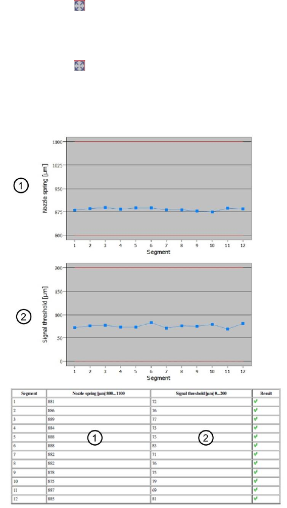
4.3.3 Explanation of Measurement Results Using Results PDF
These results can be seen if you scroll down the "Summary" menu or generate a results PDF!
Figure 19: Results PDF for nozzle spring
All ""Nozzle spring" [µm] values are relatively similar.
If the "Nozzle spring" is higher or even above the maximum tolerance threshold, this is an indication
that the DP spring system has great ease of movement.The spring may be broken! Although the
spring is fully compressed, the coils are not on top of one another due to the break.
If the "Nozzle spring" is lower or even below the minimum tolerance threshold, this is an indication that
the DP spring system has not enough ease of movement.A worn or even broken spring could be the
reason for the system blocking. The system is unable to complete the target path.