0197787-01_UM_HeadVerification_708_EN.pdf - 第29页
SIPLACE Head V erification User Manual Edition 01/2015 29 Signal Threshold [µm] = Z -Light Barrier [µm] – Z-Lo w Force [µm] 4. Results display (OK green t ick / NOK red X) 5. This diagram illustrates th e "Nozzl…
SIPLACE Head Verification
User Manual Edition 01/2015
28
13. Steps 4 – 11 are performed for each of the other segments.
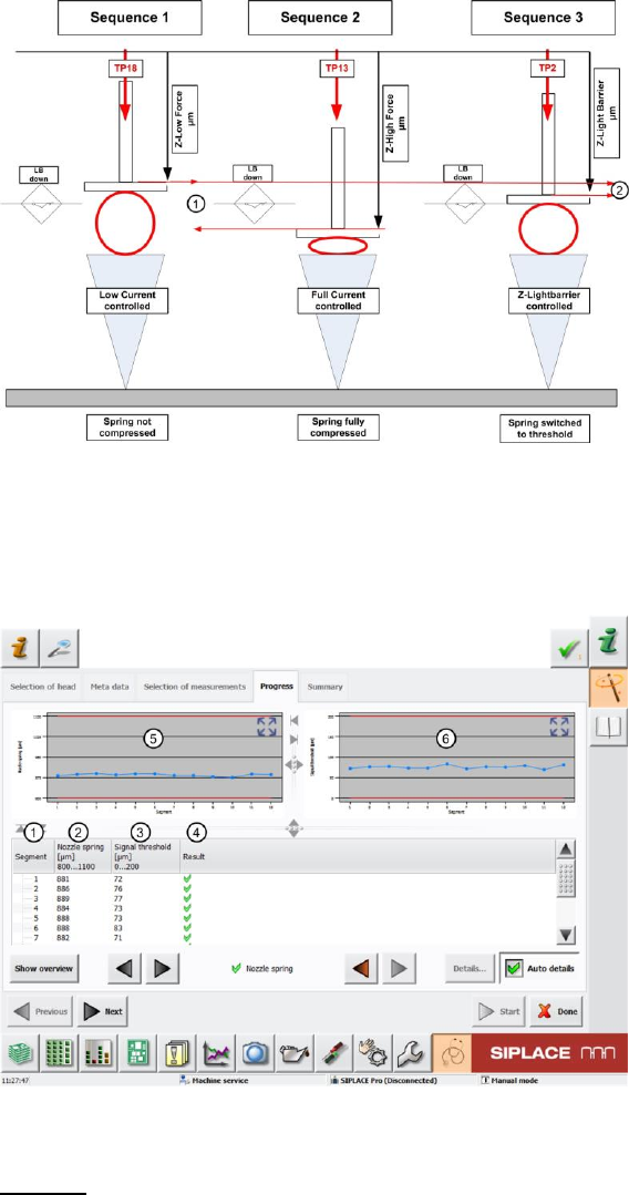
Figure 17: Nozzle spring function
4.3.2 Explanation of Measurement Results in "Progress" Menu
After completion of the measurement, the following results appear in the "Progress" menu:
Figure 18: Nozzle spring results
Legend:
1. Segment measured
2. Calculated value for complete spring deflection for segment.
This is calculated by finding the difference between the Z axis position at minimum force (no
deflection) and maximum force (complete compression of the spring)
Nozzle Spring [µm] = Z-High Force [µm] – Z-Low Force [µm]
3. Calculated value of signal threshold, which describes the breakaway torque of the spring.
This is calculated by finding the difference between the Z axis position at minimum force (no
deflection) and the Z axis position when the Z-down light barrier is triggered (breakaway
torque of spring).
SIPLACE Head Verification
User Manual Edition 01/2015
29
Signal Threshold [µm] = Z-Light Barrier [µm] – Z-Low Force [µm]
4. Results display (OK green tick / NOK red X)
5. This diagram illustrates the "Nozzle spring" values for the segments.
Blue line Nozzle spring [µm] for individual segments
Red border Min and max tolerances (in our case 800..1100µm)
Use the button to zoom in on the diagram.
6. This diagram illustrates the "Spring threshold" values for the segments.
Blue line Spring threshold [µm] for individual segments
Red border Min and max tolerances (in our case 0..200µm)
Use the button to zoom in on the diagram.
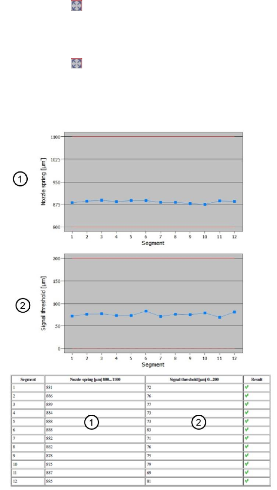
4.3.3 Explanation of Measurement Results Using Results PDF
These results can be seen if you scroll down the "Summary" menu or generate a results PDF!
Figure 19: Results PDF for nozzle spring
All ""Nozzle spring" [µm] values are relatively similar.
If the "Nozzle spring" is higher or even above the maximum tolerance threshold, this is an indication
that the DP spring system has great ease of movement.The spring may be broken! Although the
spring is fully compressed, the coils are not on top of one another due to the break.
If the "Nozzle spring" is lower or even below the minimum tolerance threshold, this is an indication that
the DP spring system has not enough ease of movement.A worn or even broken spring could be the
reason for the system blocking. The system is unable to complete the target path.

SIPLACE Head Verification
User Manual Edition 01/2015
30
The "Signal threshold" [µm] value is also the same for all segments.
A deviating value would indicate that the cover switching ring for the segment is not reliably or properly
triggering the light barrier.
4.3.4 Meaning of the Results
"Nozzle spring / Signal threshold" error at all segments:
1. Light barrier Z-down defective
Check and, if necessary, replace the Z-down light barrier
"Nozzle spring / Signal threshold" error at individual segments:
1. Segment spring is bent or mechanically damaged
Replace DP
2. The position, fixture or state of the cover switching ring is faulty
Check the fixture and, if necessary, replace the cover switching ring
4.4 "Z-Axis Movement" Measurement
The following tools are required for these measurements:
CPP: 12x nozzle type 2069 03094135-01 (vacuum nozzle red, closed)
CP20P: 20x nozzle type 4069 03106244-01 (vacuum nozzle red, closed)
CP20A: 20x nozzle type 1069 03094112-01 (vacuum nozzle red, closed)
4.4.1 Explanation of Measurement – Procedure
This measurement is used to determine the total Z travel path for a segment!
The maximum travel path determined indicates the state of the segment linear guide and also the Z
axis linear guide.
The Z axis moves with a special travel profile 3x in a free area for each segment.
The maximum travel paths determined indicate the state of the linear guides.
This proves whether each linear guide is free and has ease of movement, with no mechanical
blockages.
The results of these measurements provide feedback about the following sources of errors:
1. State of linear guide for individual segments
2. State of Z axis linear guide
Measurement steps:
1. A star and Z axis reference run is performed to bring the head into a defined initial position.
2. The head is positioned in a free area (reject bin).
3. Segment 1 is moved downwards with travel profile TP34 [TP34 LOW FORCE Z-AXIS].
This travel profile TP34 [TP34 LOW FORCE Z-AXIS] moves the Z axis downwards with low
force and creep speed.As soon as a mechanical resistance or difficulty in movement causes
an increase in the Z motor current, an end position signal is emitted.
In normal circumstances, an end position signal is emitted when the Z axis reaches the bottom
mechanical stop position.
The end position signal determined is saved as Measure 1 [µm] .
4. The Z axis then moves back up again using travel profile TP1 [TP1 ABSOLUT DEFAULT].
5. Segment 1 now moves downwards again with travel profile TP34 [TP34 LOW FORCE Z-AXIS]
and determines the end position signal again as Measure 2 [µm]
6. The Z axis then moves back up again using travel profile TP1 [TP1 ABSOLUT DEFAULT].