0197787-01_UM_HeadVerification_708_EN.pdf - 第33页
SIPLACE Head V erification User Manual Edition 01/2015 33 4.4.4 Meaning of the Results "End position Z" erro rs at all segment s: 1. Z axis linear guide is d efective Replace com plete Z axis unit "End p…
SIPLACE Head Verification
User Manual Edition 01/2015
32
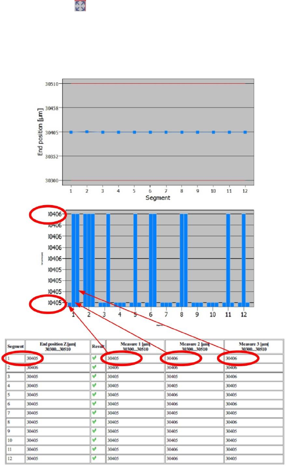
The top and bottom diagram borders are based on the dispersion of results for all "Measure 1"
– "Measure 3" values, which is why the deviation in bar lengths may be confusing!
Use the button to zoom in on the diagram.
4.4.3 Explanation of Measurement Results Using Results PDF
These results can be seen if you scroll down the "Summary" menu or generate a results PDF!
Figure 21: Results PDF for Z-movement
The average values from the three Measure 1- Measure 3 values provides the End position Z value.
This value shows whether a segment can be easily moved along the entire constructive travel path.
The End position Z value and the three individual measurements Measure 1 – Measure 3 must all
be within the tolerance range. However, slight deviations are normal.
Our example shows that "Measure 1" has a value of 30405µm. "Measure 2" – "3" each have a value
for the travel range of 30406µm.
This difference can also be seen on the bar length in the diagram.
If either "Measure1", "2" or "3" is outside the tolerance, this indicates that the guide for this segment is
defective, as a repeated ease of movement can not be proven. The DP (for CP20P/A) or the segment
guide (for CPP) will need to be replaced soon.
If all "Measure1" – "Measure3" values are outside the tolerance range, this clearly indicates that the
guide has difficulty moving.The DP (for CP20P/A) or the segment guide (for CPP) must be replaced.

SIPLACE Head Verification
User Manual Edition 01/2015
33
4.4.4 Meaning of the Results
"End position Z" errors at all segments:
1. Z axis linear guide is defective
Replace complete Z axis unit
"End position Z" errors at individual segments:
1. If all "Measure 1" – "Measure 3" values are outside the tolerance, this indicates that the linear
guide of the segment (CPP) or the DP (CP20P/A) are defective
CPP: Replace the linear guide for the segment
CP20P/A: Replace the DP
2. If only "Measure1", "2" or "3" are outside the tolerance, an increasing difficulty of movement is
present.
CPP: Prepare replacement of the linear guide for the segment
CP20P/A: Prepare replacement of the DP
4.5 "Cover Switching Ring Mounting" Measurement
The following tools are required for these measurements:
CP20A: 20x nozzle type 1069 03094112-01 (vacuum nozzle red, closed)
4.5.1 Explanation of Measurement – Procedure
This measurement checks the correct installation of the cover switching rings. The cover switching
rings are a key part of the CP20A heads and are responsible for correct triggering of the Z-down light
barrier.
The voltage value for the Z-down light barrier is checked, while the segment is rotated in 90° steps.
This gives an idea of whether the cover switching ring is defective, tilted or dirty.
The results of these measurements provide feedback about the following sources of errors:
1. State of Z-down light barrier
2. Installation error for cover switching ring on DP
3. State of cover switching rings

SIPLACE Head Verification
User Manual Edition 01/2015
34
Measurement steps:
1. The Z axis remains in the top position
2. All DPs are referenced so that they are at 0°.
3. Segment 1 is rotated into the placement position but remains in the top position.
4. Measurement 0°:
The Z-down light barrier is triggered and measures the distance to the cover switching ring for
segment 1.The Z-down light barrier provides an analog voltage value for the distance. This
value is known as Measure 1 [mV].
This 0° value is also used as a reference value for checking the general functionality of the
light barriers.This reference value is compared to a theoretical value in the machine data.
5. Rotate segment 1 to 90°
6. Measurement 90°:
The Z-down light barrier is triggered and measures the distance to the cover switching ring for
segment 1.The Z-down light barrier provides an analog voltage value for the distance. This
value is known as Measure 2 [mV].
7. Rotate segment 1 to 180°
8. Measurement 180°:
The Z-down light barrier is triggered and measures the distance to the cover switching ring for
segment 1.The Z-down light barrier provides an analog voltage value for the distance. This
value is known as Measure 3 [mV].
9. Rotate segment 1 to 270°
10. Measurement 270°:
The Z-down light barrier is triggered and measures the distance to the cover switching ring for
segment 1.The Z-down light barrier provides an analog voltage value for the distance. This
value is known as Measure 4 [mV].
11. The whole rotation of the cover switching ring is known as the Mounting variation [µm]
value.
This value is calculated using the minimum and maximum results for "Measure 1" – "Measure
4". The difference between the lowest and highest voltage value provides a value which
describes the eccentricity of the cover switching ring and the rotation of the cover switching
ring around the central axis of the DP (sway).
If this value is higher than a defined tolerance, this indicates that the cover switching ring is
not correctly fitted or that it is defective.
12. Measurements 4-11 are now performed for all other segments.