0197787-01_UM_HeadVerification_708_EN.pdf - 第38页
SIPLACE Head V erification User Manual Edition 01/2015 38 5. The gantry is then m oved again o ver the height referen ce run position on the conve yor side. 6. The Z axis is m oved downwards using th e travel profile T P…

SIPLACE Head Verification
User Manual Edition 01/2015
37
4.6 "Air & Vacuum with Head Sensors" Measurement
The following tools are required for these measurements:
CPP: 12x nozzle type 2057 03070280-01 (calibration nozzle)
CP20P: 20x nozzle type 4235 03098748-01 (calibration nozzle)
CP20A: 20x nozzle type 1235 03015222-01 (calibration nozzle)
1x calibration tool CPP 03010565-01 or
1x calibration tool C&P20A/P 03034148-01
4.6.1 Explanation of Measurement – Procedure
This measurement is used to determine the vacuum and air blast properties for the placement head
and its segments.The individual measurement steps are used to pinpoint defective components in a
placement head which are impairing the vacuum at the head and therefore causing placement and
pickup errors. In addition, the air blast values are also examined for the placement head.
Firstly, the open and closed vacuum values are determined for the segment, followed by the holding
circuit values for the individual segments.Each segment then has an air blast applied to it. To examine
the vacuum at the segment precisely, the height reference run position is approached and the vacuum
measured at 0°, 90°, 180° and 270° for each segment.This is the only way to reliably check the
vacuum values across the entire DP area, as the rotary system must be completely sealed over the
full 360°.
The results of these measurements are provide feedback about the following sources of errors:
1. State of segment filter disks
2. State of vacuum air-tightness for segment (rotation through 360°)
3. State of vacuum hoses
4. Functionality of vacuum pump (optional)
5. Sate of holding circuit
6. Leaky vacuum nozzle
Measurement procedure details (Example of CPP):
1. The head moves with the calibration nozzles over the nozzle station and moves the Z axis
downwards with the travel profile TP13 [NOZZLE CHANGER DOWN]. This sequence presses
the nozzles firmly against the nozzle seat of the segment again, to achieve the best possible
seal between the nozzle and segment.
2. A clean-up command is then executed at the top position of each segment, to blow any
contaminants off the nozzle and segment and to create the best possible conditions for the
following measurements.
3. The head then moves over the height reference run position on the conveyor side. The Z axis
is moved to the height reference run position in light barrier mode, using the travel profile TP5
[TP5 LIGHT BARRIER].While the Z axis is moving downwards, the vacuum is enabled for this
segment and the Vacuum open [mbar] value is determined.When the Z axis meets the
height reference run position on the conveyor side, the light barrier Z-down is triggered and an
end position signal is emitted.The Vacuum closed [mbar] value is measured there.Both
vacuum values have therefore been determined, with uncovered nozzle (Vacuum open) and
covered nozzle (Vacuum closed).
The Difference "Vacuum closed [mbar] – Vacuum open [mbar]" is used to calculate the
Vacuum delta value in mbar. A certain value must be reached to confirm a reliably
functioning vacuum at the nozzle. The Vacuum delta value in mbar is defined by the type of
nozzle and its cross-section. All thresholds are defined for the calibration nozzle used here.
4. The gantry then moves over the park position and determines the holding circuit values for
each segment. The Holding (nozzle open) [mbar] value determined describes the vacuum
present at an uncovered nozzle, while it is being rotated from the pickup to the placement
cycle (holding circuit). This value should verify the holding force at the nozzle during the
rotation of the star from the pickup to the placement position.
The Open dev. [mbar] value also determined here can not be explained further.
SIPLACE Head Verification
User Manual Edition 01/2015
38
5. The gantry is then moved again over the height reference run position on the conveyor side.
6. The Z axis is moved downwards using the travel profile TP5 [TP5 LIGHT BARRIER] and
segment 1 picks up the calibration component (in CPP simulated on hardened height
reference run fiducial) with 0°. At the same time, the Vacuum 0° [mbar] value is measured for
the emitted light barrier Z-down end position signal.
7. The Z axis then moves back to the top position.
8. The Z axis is moved downwards again using the travel profile TP5 [TP5 LIGHT BARRIER] and
segment 1 picks up the calibration component once more (in CPP simulated on hardened
height reference run fiducial) with 90°. At the same time, the Vacuum 90° [mbar] value is
measured for the emitted light barrier Z-down end position signal.
9. The Z axis then moves back to the top position.
10. The Z axis is moved downwards again using the travel profile TP5 [TP5 LIGHT BARRIER] and
segment 1 picks up the calibration component once more (in CPP simulated on hardened
height reference run fiducial) with 180°. At the same time, the Vacuum 180° [mbar] value is
measured for the emitted light barrier Z-down end position signal.
11. The Z axis then moves back to the top position.
12. The Z axis is moved downwards again using the travel profile TP5 [TP5 LIGHT BARRIER] and
segment 1 picks up the calibration component once more (in CPP simulated on hardened
height reference run fiducial) with 270°. At the same time, the Vacuum 270 [mbar] value is
measured for the emitted light barrier Z-down end position signal.
13. The Z axis then moves back to the top position and the star steps segment 2 into the pickup
position.
14. Steps 6-12 are now performed for all other head segments.
15. The values determined for the four angle measurements Vacuum 0°- Vacuum 270° [mbar]
are used to calculated the maximum deviation Delta vac. 0-270° [mbar]. The maximum
dispersion from minimum to maximum shows the air-tightness for that segment over 360°.
16. The head then moves over the calibration component and picks it up with travel profile TP5
[TP5 LIGHT BARRIER]. At the same time, the Vacuum calib part [mbar] value is measured
at emission of the end position signal light barrier Z-down, for use as a reference for
components picked up.
This value at calibration component pickup Vacuum calib part [mbar] is compared with the
Vacuum closed [mbar] value from the open-closed measurement. The difference from
Vacuum closed [mbar] - Vacuum calib part [mbar] provides the Delta calib-closed [mbar]
value.
Delta calib-closed [mbar] is an indicator for the segment (nozzle) that the vacuum values
determined during nozzle reference run correspond to the vacuum values during component
pickup.
17. After each placing down of the calibration component, the vacuum is switched off and the
vacuum value is measured at the nozzle to make sure that it is reliably reduced and to ensure
that no components remain hanging from the nozzle, due to an existing underpressure.This
value is known as Calib part dev [mbar].
18. Following this, an air blast of 200mbar is switched through to each segment, to measure the
air blast value which actually arrives at the segment.This value is known as Air [mbar] and
indicates that the air blast is switched through correctly for rejection or switchover between
holding and placement.
19. After switching off the air blast, it is measured once again to see how it is reduced at the
nozzle tip. The value measured is known as Vacuum zero [mbar] and indicates how reliably
the pressure is reduced at the nozzle tip.
SIPLACE Head Verification
User Manual Edition 01/2015
39
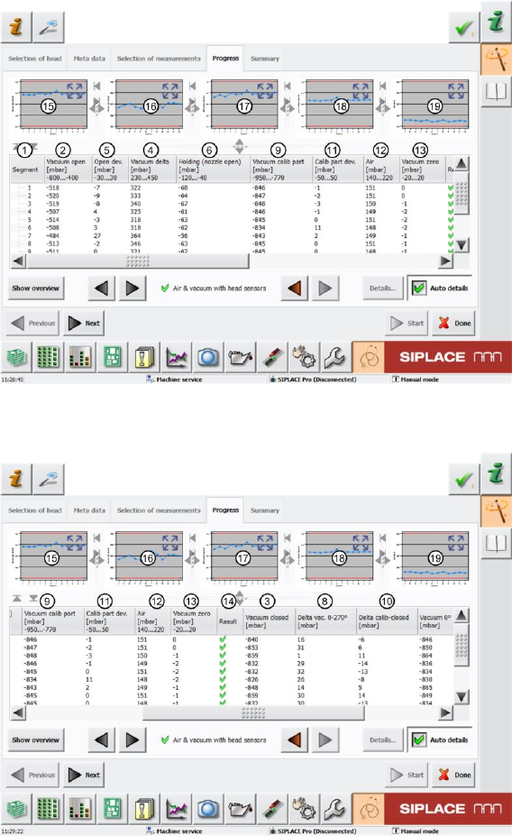
4.6.2 Explanation of Measurement Results in Progress Menu
After completion of the measurement, the following results appear in the "Progress" menu:
Figure 24: Air & vacuum with head sensors 1 result
Figure 25: Air & vacuum with head sensors 2 result