0197787-01_UM_HeadVerification_708_EN.pdf - 第40页
SIPLACE Head V erification User Manual Edition 01/2015 40 Figure 26 : Air & va cuum with head sensors 3 result Legend: 1. Segment m easured 2. Value determ ined Vacuum open [mbar] This value is determ ined when the…
SIPLACE Head Verification
User Manual Edition 01/2015
39
4.6.2 Explanation of Measurement Results in Progress Menu
After completion of the measurement, the following results appear in the "Progress" menu:
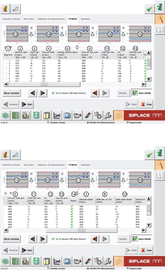
Figure 24: Air & vacuum with head sensors 1 result
Figure 25: Air & vacuum with head sensors 2 result
SIPLACE Head Verification
User Manual Edition 01/2015
40
Figure 26: Air & vacuum with head sensors 3 result
Legend:
1. Segment measured
2. Value determined Vacuum open [mbar]
This value is determined when the Z axis moves downwards with the travel profile TP5 and
while the vacuum is measured at the open nozzle. This value must be within a plausible
tolerance (in this case for the CPP head with nozzle 2057 -800…400mbar).
3. Value determined Vacuum closed [mbar]
This value is determined when the Z axis meets the component (in this measurement at the
height reference run position), the light barrier Z-down end position signal has been emitted
and the nozzle is understood to be closed. This is an absolute value and must not be within a
tolerance!
4. The Vacuum delta [mbar] value is calculated by finding the difference between the Vacuum
closed [mbar] (3) values and the Vacuum open [mbar] (2) value. Since the threshold value
for Vacuum open [mbar] is prescribed by the head and nozzle type parameters and the
Vacuum closed [mbar] value is an actual vacuum value at the closed nozzle during pickup,
the Vacuum delta [mbar] value is also within a defined tolerance.
(in this case for CPP head with nozzle 2057 230…450mbar).
Vacuum delta [mbar] = Vacuum closed [mbar] – Vacuum open [mbar]
5. The Open dev. [mbar] will not be explained further and is not currently used for the head
verification.
6. The Holding (nozzle open) [mbar] describes the value measured at the vacuum present at
an open nozzle during rotation of the complete holding circuit.
This value depends on the use of a vacuum pump and must also be within a plausible
tolerance.
(in this case for CPP head with nozzle 2057 -120..-40mbar)
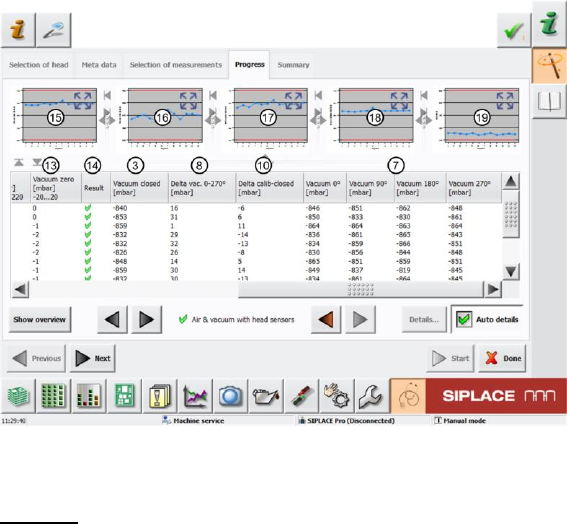
7. This shows the vacuum values determined for the closed nozzle during simulated pickup
(either calibration component or height reference run plate) at the moment of light barrier Z-
down action (end position signal) in the pickup angles 0°, 90°, 180° and 270°. These "Vacuum
0°"-"Vacuum 270°" values provide an overview of the vacuum at different pickup and
placement angles.
8. The Delta vac. 0-270° [mbar] value is calculated by finding the difference between the lowest
and highest values from the "Vacuum 0°"-"Vacuum 270°" (7) measurement.
If this value is exceptionally high, compared to other segments, this indicates that the segment
has a problem at one of the angles. The angle overview (7) helps you to identify where the

SIPLACE Head Verification
User Manual Edition 01/2015
41
problem is.The dispersion should be as small as possible, as this shows a constant vacuum
behavior across the 360°.
Delta vac. 0-270° [mbar] = max. Vacuum 0°-270° [mbar] - min. Vacuum 0°-270° [mbar]
9. During calibration component pickup, the Vacuum calib part [mbar] value is used as a
reference value for the vacuum at closed nozzle pickup. The value must be within a tolerance
of -950..-770mbar.
10. The Delta calib-closed [mbar] is calculated by finding the difference between the Vacuum
Calib part [mbar] (9) and the Vacuum closed [mbar] (3) values. This value is used as a
comparative value to check whether the vacuum value during pickup is correct and whether
the system is working reliably.
Delta calib-closed [mbar] = Vacuum calib part [mbar] (9) – Vacuum closed [mbar] (3)
11. The Calib part dev. [mbar] value describes how reliably the vacuum is reduced at the nozzle.
12. The Air [mbar] measurement checks the air blast pressure which is actually at the open
nozzle when the gripper is switched on with 200 mbar blast pressure.
The value must be within a tolerance of 140..220mbar.
13. After switching off the air blast, the pressure is measured again at the nozzle tip. This value
Vacuum zero [mbar] shows how the air blast pressure has been reduced at the nozzle tip.
14. Results display (OK green tick / NOK red X)
15. This diagram illustrates the "Vacuum open [mbar]" values for the segments.
Blue line Vacuum open [mbar]
Red border Min and max tolerances (in our case -680..-400mbar)
Use the button to zoom in on the diagram.
16. This diagram illustrates the "Vacuum delta [mbar]" values for the segments.
Blue line Vacuum delta [mbar]
Red border Min and max tolerances (in our case 100..220mbar)
Use the button to zoom in on the diagram.
17. This diagram illustrates the "Holding open [mbar]" values for the segments.
Blue line Holding (open) [mbar]
Red border Min and max tolerances (in our case -180..-60mbar)
Use the button to zoom in on the diagram.
18. This diagram illustrates the "Vacuum calib part [mbar]" values for the segments.
Blue line Vacuum calib part [mbar]
Red border Min and max tolerances (in our case -900..-680mbar)
Use the button to zoom in on the diagram.
19. This diagram illustrates the "Air [mbar]" values for the segments.
Blue line Air [mbar]
Red border Min and max tolerances (in our case 190..250mbar)
Use the button to zoom in on the diagram.