0197787-01_UM_HeadVerification_708_EN.pdf - 第45页
SIPLACE Head V erification User Manual Edition 01/2015 45 Figure 29 : Head endur ance run 01 005_2 result Legend: 1. Segment m easured 2. Total number of cycles 3. Value determ ined Z dow n delta pick [µm] This value i…
SIPLACE Head Verification
User Manual Edition 01/2015
44
The positioning time for rotation of the DP at 180° (place) after 0° (pickup) is also determined.
7. Segment 1 is then moved back up again with travel profile TP1.
8. Placement:
Segment 1 is now moved downwards with travel profile TP34 [TP34 01005 CRAWL] and a DP
placement angle of 180° and is contactlessly positioned at the determined Z pickup position.
The actual Z position determined when the end position signal is emitted is known as Z-Place
[µm].
The positioning time for rotation of the DP at 0° (pickup) after 180° (place) is also determined.
9. Segment 1 is then moved back up again with travel profile TP1.
10. This procedure is now executed 30x for segment 1, which means a total of 60x Z axis
movements (30x pickup / 30x place) and also 60x DP positioning times.
11. All pickup positions Z-Pick [µm] are saved internally and the minimum (Z min pick [µm]) and
maximum (Z max pick [µm]) positions are used for the analysis.
12. All placement positions Z-Place [µm] are saved internally and the minimum (Z min place
[µm]) and maximum (Z max place [µm]) positions are used for the analysis.
13. The positioning times for rotation of each segment by 180° are also analyzed, to provide a
minimum (Min DP Time [ms]) and maximum (Max DP Time [ms]) value for each segment.
14. The star now turns segment 2 into the placement position
15. Measurements 6-14 are now performed for all other segments.
4.7.2 Explanation of Measurement Results in "Progress" Menu
After completion of the measurement, the following results appear in the "Progress" menu:
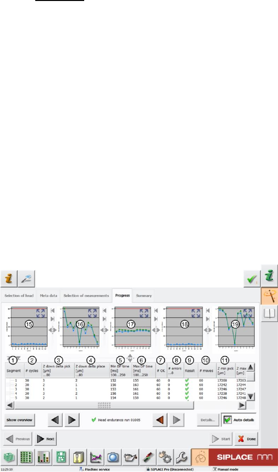
Figure 28: Head endurance run 01005_1 result
SIPLACE Head Verification
User Manual Edition 01/2015
45
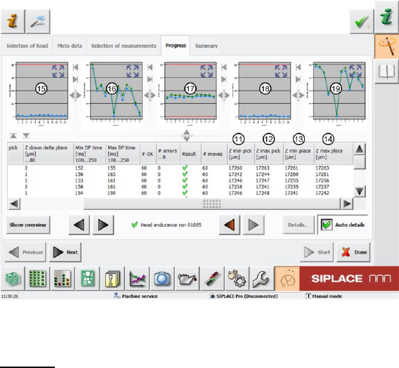
Figure 29: Head endurance run 01005_2 result
Legend:
1. Segment measured
2. Total number of cycles
3. Value determined Z down delta pick [µm]
This value is calculated by finding the difference between the lowest (Z min pick [µm] (11))
and the highest (Z max pick [µm] (12)) Z axis positioning value during the pickup cycles.
This value must be within a plausible tolerance (in this case 0..80µm).
Z down delta pick [µm] = Z max pick [µm] - Z min pick [µm]
4. Value determined Z down delta place [µm]
This value is calculated by finding the difference between the lowest (Z min place [µm]
(13)) and the highest (Z max place [µm] (14)) Z axis positioning value during the pickup
cycles.
This value must be within a plausible tolerance (in this case 0..80µm)!
Z down delta place [µm] = Z max place [µm] - Z min place [µm]
5. The Min DP time [ms] value is the shortest DP positioning time reached during positioning at
180°. This value must be within a plausible tolerance (in this case 100..250µm)!
6. The Max DP time [ms] value is the longest DP positioning time reached during positioning at
180°. This value must be within a plausible tolerance (in this case 100..250µm)!
7. Results display for number of successful strokes
8. Number of errors during 30x total cycles.
9. Results display (OK green tick / NOK red X)
10. Number of individual Z axis movements (in our case 30x down + 30x up = 60)
11. Z min pick [µm] is the lowest Z axis positioning value achieved during the pickup cycles.This
value is used to calculate the Z down delta pick [µm] (3) value.
12. Z max pick [µm] is the highest Z axis positioning value achieved during the pickup
cycles.This value is used to calculate the Z down delta pick [µm] (3) value.
13. Z min place [µm] is the lowest Z axis positioning value achieved during the placement
cycles.This value is used to calculate the Z down delta place [µm] (4) value.
14. Z max place [µm] is the highest Z axis positioning value achieved during the placement
cycles.This value is used to calculate the Z down delta place [µm] (4) value.
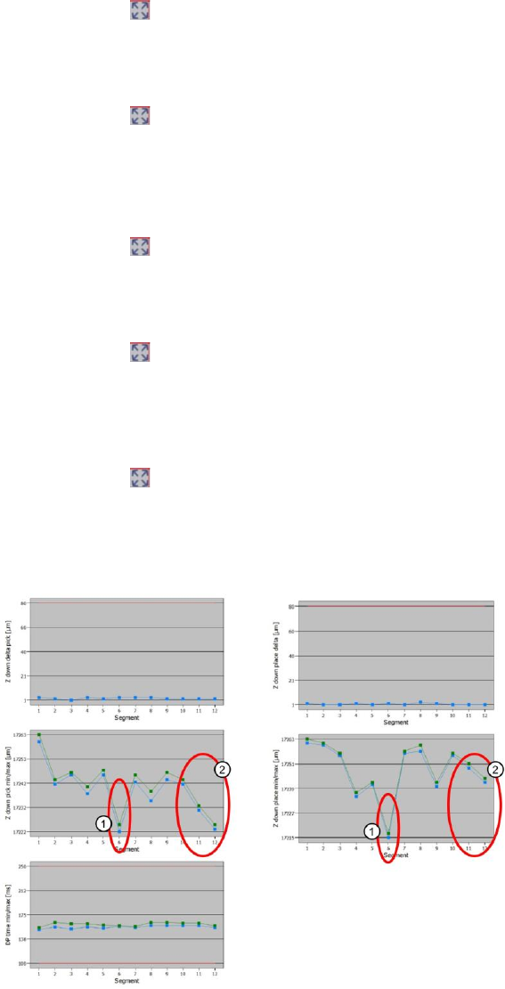
15. This diagram illustrates the "Z down delta pick [µm] (3)" values for the segments.
Blue line Z down delta pick [µm]
Red border Min and max tolerances (in our case 0..80µm)
SIPLACE Head Verification
User Manual Edition 01/2015
46
Use the button to zoom in on the diagram.
16. This diagram illustrates the "Z down delta pick min/max [µm] (11,12)" values for the segments.
Blue line Z down pick min [µm]
Green line Z down pick max [µm]
Use the button to zoom in on the diagram.
17. This diagram illustrates the "DP time min/max [ms] (5,6)" values for the segments.
Blue line DP time min [ms]
Green line DP time max [ms]
Red border Min and max tolerances (in our case 100..250ms)
Use the button to zoom in on the diagram.
18. This diagram illustrates the "Z down delta place [µm] (4)" values for the segments.
Blue line Z down delta pick [µm]
Red border Min and max tolerances (in our case 0..80µm)
Use the button to zoom in on the diagram.
19. This diagram illustrates the "Z down delta place min/max [µm] (13,14)" values for the
segments.
Blue line Z down place min [µm]
Green line Z down place max [µm]
Use the button to zoom in on the diagram.
4.7.3 Explanation of Measurement Results Using Results PDF
These results can be seen if you scroll down the "Summary" menu or generate a results PDF!
Figure 30: Results PDF for head endurance run 01005_1