0197787-01_UM_HeadVerification_708_EN.pdf - 第51页
SIPLACE Head V erification User Manual Edition 01/2015 51 4.8.3 Explanation of Measurement Results Using Results PDF These results can b e seen if you scroll down the "Sum mary" menu or generat e a results PDF!…

SIPLACE Head Verification
User Manual Edition 01/2015
50
This value must be within a plausible tolerance (in this case 0..150µm)!
Z down delta place [µm] = Z max place [µm] - Z min place [µm]
5. The Min DP time [ms] value is the shortest DP positioning time reached during positioning at
180°. This value must be within a plausible tolerance (in this case 100..250µm)!
6. The Max DP time [ms] value is the longest DP positioning time reached during positioning at
180°. This value must be within a plausible tolerance (in this case 100..250µm)!
7. Results display for number of successful strokes
8. Number of errors during 50x total cycles.
9. Results display (OK green tick / NOK red X)
10. Number of individual Z axis movements (in our case 50x down + 50x up = 100)
11. Z min pick [µm] is the lowest Z axis positioning value achieved after switching the Z-down
light barrier during the pickup cycles.This value is used to calculate the Z down delta pick
[µm] (3) value.
12. Z max pick [µm] is the highest Z axis positioning value achieved after switching the Z-down
light barrier during the pickup cycles.This value is used to calculate the Z down delta pick
[µm] (3) value.
13. Z min place [µm] is the lowest Z axis positioning value achieved after switching the Z-down
light barrier during the placement cycles.This value is used to calculate the Z down delta
place [µm] (4) value.
14. Z max place [µm] is the highest Z axis positioning value achieved after switching the Z-down
light barrier during the placement cycles.This value is used to calculate the Z down delta
place [µm] (4) value.
15. This diagram illustrates the "Z down delta pick [µm] (3)" values for the segments.
Blue line Z down delta pick [µm]
Red border Min and max tolerances (in our case 0..150µm)
Use the button to zoom in on the diagram.
16. This diagram illustrates the "Z down delta pick min/max [µm] (11,12)" values for the segments.
Blue line Z down pick min [µm]
Green line Z down pick max [µm]
Use the button to zoom in on the diagram.
17. This diagram illustrates the "DP time min/max [ms] (5,6)" values for the segments.
Blue line DP time min [ms]
Green line DP time max [ms]
Red border Min and max tolerances (in our case 100..250ms)
Use the button to zoom in on the diagram.
18. This diagram illustrates the "Z down delta place [µm] (4)" values for the segments.
Blue line Z down delta pick [µm]
Red border Min and max tolerances (in our case 0..150µm)
Use the button to zoom in on the diagram.
19. This diagram illustrates the "Z down delta place min/max [µm] (13,14)" values for the
segments.
Blue line Z down place min [µm]
Green line Z down place max [µm]
Use the button to zoom in on the diagram.
SIPLACE Head Verification
User Manual Edition 01/2015
51
4.8.3 Explanation of Measurement Results Using Results PDF
These results can be seen if you scroll down the "Summary" menu or generate a results PDF!
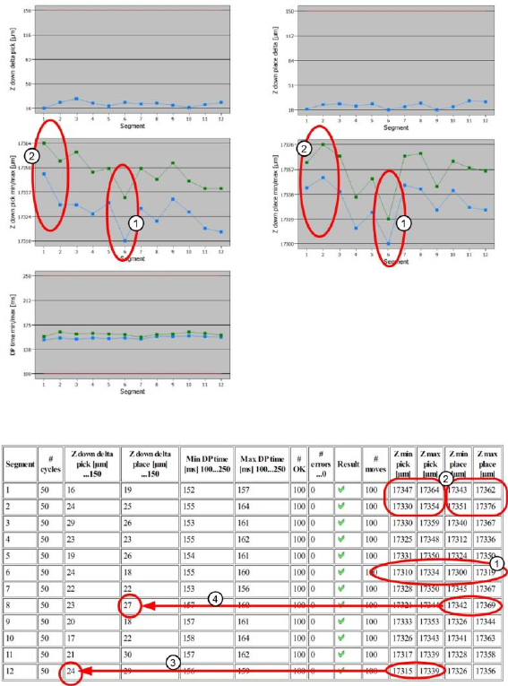
Figure 34: Results PDF for head endurance run LS_1
Figure 35: Results PDF for head endurance run LS_2
Point 1:
The "Z down pick min/max" and "Z down place min/max" diagrams, plus the corresponding
measurements in the table, indicate that segment 6 deviates from all other segments both during
pickup and during placement! During both movements, this segment was not able to move as far
downwards as the other segments.
This might be due to difficulty moving the segment linear guide, to a defective cover switching ring
causing the light barrier to switch earlier or to the light barrier window in the CPP segment being dirty.
Point 2:
The "Z down pick min/max" and "Z down place min/max" diagrams, plus the corresponding
measurements in the table, indicate that segments 1 and 2 deviate significantly between pickup and
placement. The Z axis does not move as far downwards during pickup as it does during placement.
One possible cause could be that the DP linear guide have difficulty moving and that the segment or
DP linear guide may soon need replacing.
Point 3:
We can see here how the "Z down delta pick [ms]" value is calculated using the two threshold values
"Z min pick [ms]" and "Z max pick [max]". A value which is leaning towards the upper threshold (in this
example 150µm), indicates a problem with the linear guide for that segment.

SIPLACE Head Verification
User Manual Edition 01/2015
52
Point 4:
We can see here how the "Z down delta place [ms]" value is calculated using the two threshold values
"Z min place [ms]" and "Z max place [max]". A value which is leaning towards the upper threshold (in
this example 150µm), indicates a problem with the linear guide for that segment.
4.8.4 Meaning of the Results
"Z down delta pick [µm]" and "Z down delta place [µm]" errors at all segments:
1. Z motor defective Replace Z motor
2. Z motor linear guide has difficulty moving Replace Z motor
3. Read unit of Z motor is dirty Clean the read unit
4. Light barrier Z down dirty/defective Clean/replace the light barrier
"Z down delta pick [µm]" and "Z down delta place [µm]" errors at individual segments:
1. DP linear guide has difficulty moving Replace DP
2. Linear guide for segment has difficulty moving Replace linear guide for segment
3. Cover switching ring defective or incorrectly fitted Replace cover switching ring
4. Light barrier in segment dirty Clean light barrier through window
"Min DP time [ms]" or "Max DP time [ms]" errors at individual segments:
1. Internal DP/segment problem Replace DP/segment
4.9 "Segment Offset Up & Down (Fast)" Measurement
The following tools are required for these measurements:
CPP: 12x nozzle type 2057 03070280-01 (calibration nozzle)
CP20P: 20x nozzle type 4235 03098748-01 (calibration nozzle)
CP20A: 20x nozzle type 1235 03015222-01 (calibration nozzle)
1x calibration component CPP 03010565-01
or
1x calibration component C&P20A/P 03034148-01
4.9.1 Explanation of Measurement – Procedure
The "Segment offset up & down (fast)" measurement is a quick test to determined how far outside its
rotation axis a segment is. If this measurement shows that a segment is outside the tolerance
threshold, meaning that it is badly deformed, all subsequent measurements will be terminated, as the
head is no longer able to produce (due to this segment.)The segment must be immediately replaced,
before other measurements can be performed.
This eccentricity of the segment center to the middle of the camera is known as the segment
offset.The "segment offset up" describes the rotation (offset) of the segment in docked state to the
component camera. The "segment offset down" describes the rotation of the segment in the bottom
position. This position then illustrates the eccentricity of the segment axis in the pickup or placement
position, meaning the offset between the component and PCB camera. This measurement is important
and enables the machine to calculate this displacement into the target positions during pickup and
placement, thereby increasing the pickup or placement accuracy.The "Segment offset up & down
(fast)" measurement is performed for each segment at an angle of 0°, in the top or bottom position and
provides a quick idea of the rough segment offset, so that additional measurements to establish a
defective segment are not always needed.
The results of these measurements provide feedback about the following sources of errors:
1. Deformed segments
2. Defective Z linear guides for DP / segments (worn out / loose)