0197787-01_UM_HeadVerification_708_EN.pdf - 第53页
SIPLACE Head V erification User Manual Edition 01/2015 53 Measurement steps: 1. Firstly, the exact position of the calibration com ponent in the calibration bag is d etermined with the PCB cam era, as the actual positi o…

SIPLACE Head Verification
User Manual Edition 01/2015
52
Point 4:
We can see here how the "Z down delta place [ms]" value is calculated using the two threshold values
"Z min place [ms]" and "Z max place [max]". A value which is leaning towards the upper threshold (in
this example 150µm), indicates a problem with the linear guide for that segment.
4.8.4 Meaning of the Results
"Z down delta pick [µm]" and "Z down delta place [µm]" errors at all segments:
1. Z motor defective Replace Z motor
2. Z motor linear guide has difficulty moving Replace Z motor
3. Read unit of Z motor is dirty Clean the read unit
4. Light barrier Z down dirty/defective Clean/replace the light barrier
"Z down delta pick [µm]" and "Z down delta place [µm]" errors at individual segments:
1. DP linear guide has difficulty moving Replace DP
2. Linear guide for segment has difficulty moving Replace linear guide for segment
3. Cover switching ring defective or incorrectly fitted Replace cover switching ring
4. Light barrier in segment dirty Clean light barrier through window
"Min DP time [ms]" or "Max DP time [ms]" errors at individual segments:
1. Internal DP/segment problem Replace DP/segment
4.9 "Segment Offset Up & Down (Fast)" Measurement
The following tools are required for these measurements:
CPP: 12x nozzle type 2057 03070280-01 (calibration nozzle)
CP20P: 20x nozzle type 4235 03098748-01 (calibration nozzle)
CP20A: 20x nozzle type 1235 03015222-01 (calibration nozzle)
1x calibration component CPP 03010565-01
or
1x calibration component C&P20A/P 03034148-01
4.9.1 Explanation of Measurement – Procedure
The "Segment offset up & down (fast)" measurement is a quick test to determined how far outside its
rotation axis a segment is. If this measurement shows that a segment is outside the tolerance
threshold, meaning that it is badly deformed, all subsequent measurements will be terminated, as the
head is no longer able to produce (due to this segment.)The segment must be immediately replaced,
before other measurements can be performed.
This eccentricity of the segment center to the middle of the camera is known as the segment
offset.The "segment offset up" describes the rotation (offset) of the segment in docked state to the
component camera. The "segment offset down" describes the rotation of the segment in the bottom
position. This position then illustrates the eccentricity of the segment axis in the pickup or placement
position, meaning the offset between the component and PCB camera. This measurement is important
and enables the machine to calculate this displacement into the target positions during pickup and
placement, thereby increasing the pickup or placement accuracy.The "Segment offset up & down
(fast)" measurement is performed for each segment at an angle of 0°, in the top or bottom position and
provides a quick idea of the rough segment offset, so that additional measurements to establish a
defective segment are not always needed.
The results of these measurements provide feedback about the following sources of errors:
1. Deformed segments
2. Defective Z linear guides for DP / segments (worn out / loose)

SIPLACE Head Verification
User Manual Edition 01/2015
53
Measurement steps:
1. Firstly, the exact position of the calibration component in the calibration bag is determined with
the PCB camera, as the actual position (the exact center and position), and is then adopted as
the pickup position. This center is determined using 4 points at the corners of the calibration
component.
2. Segment 1 now moves downwards at an angle of 0° and picks the calibration component up
from the pickup position determined (calibration component center).
3. Segment 1 is moved upwards again.
4. Segment 1 is rotated by the star over the component camera.
5. The component camera measures the four calibration component structure fiducials to
determine the exact position of the calibration component to the camera center, thereby
optically centering the calibration component.The offset values determined here are saved as
Up X [µm] and Up Y [µm]. This value now describes the eccentricity of the calibration
component to the camera center.This value provides the "Segment offset up" for segment 1 at
0°, as we can assume that segment 1 picked up the calibration component exactly in the
center. The offset values determined are calculated into the following placement (putdown) of
the calibration component (calibration bag) as correction values.
6. The star now rotates the segment with the calibration component back into the placement
position.
7. Segment 1 and the Z axis are moved downwards and the calibration component is placed in
the calibration bag at an angle of 0° (DP/segment angle) and with the corrected offset values
Up X [µm] and Up Y [µm], as a placement position.
8. The PCB camera now moves over the calibration component and once more determines the
four points in the calibration component corners, to find the exact position of the calibration
component in the bag. This provides the offset values Down X [µm] and Down Y [µm], which
describe the eccentricity of the calibration component to the PCB camera center. This value
describes exactly the offset of the segment 1 center at a placement angle of 0°, when
segment 1 is in the placement position. This provides the exact displacement of segment 1 at
a placement angle of 0°, describing how much the Z linear guide has changed the segment
position at the top to the segment position at the bottom.This deviation also describes the
offset of the component camera to the PCB camera for this segment.
9. The values determined for segment 1 Down X [µm] and Down Y [µm] are taken as an
absolute 0 for all other calculations of all segment offsets. The "Segment offset down" for
segment 1 is the reference value as all other offsets for all other segments refer to this initial
value.
10. The calibration component position determined is now used again as actual pickup position for
the following measurement.
11. Segment 2 now picks up at 0°.
12. Steps 2-10 are performed for all segments.
13. The calibration component stays in its position at 0° for the entire measurement and does not
change its angle!
SIPLACE Head Verification
User Manual Edition 01/2015
54
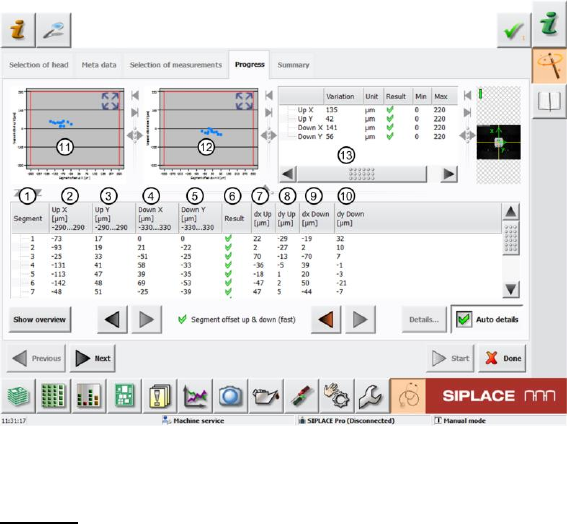
4.9.2 Explanation of Measurement Results in "Progress" Menu
After completion of the measurement, the following results appear in the "Progress" menu:
Figure 36: Segment offset up and down (fast) result
Legend:
1. Segment measured
2. Calculated "Segment offset up" value Up X [µm] from measurement at an angle of 0°. This
deviation is determined with the value dx Up [µm] (7), as the actual segment offset measured
to the component camera center. The calculated "Segment offset up" value Up X [µm] is
calculated from the offset between the component and PCB camera.
The segment offset values Up X [µm] determined must always be in a certain tolerance range
(in our example -290..290µm). This value defines a permissible segment offset within the
construction and production tolerances, which can still be compensated by the software. If the
segment offset values are outside the tolerances, we can assume that the segment has been
mechanically deformed, so that it has been bent and is no longer suitable for accurate
placement.
3. Calculated "Segment offset up" value Up Y [µm] from measurement at an angle of 0°. This
deviation is determined with the value dy Up [µm] (8), as the actual segment offset measured
to the component camera center. The calculated "Segment offset up" value Up Y [µm] is
calculated from the offset between the component and PCB camera.
The segment offset values Up Y [µm] determined must always be in a certain tolerance range
(in our example -290..290µm). This value defines a permissible segment offset within the
construction and production tolerances, which can still be compensated by the software. If the
segment offset values are outside the tolerances, we can assume that the segment has been
mechanically deformed, so that it has been bent and is no longer suitable for accurate
placement.
4. Calculated "Segment offset down" value Down X [µm] from measurement at an angle of 0°.
This value is calculated from the actual "Segment offset down" value dx Down [µm] for this
segment. This offset is illustrated in the value dx Down [µm] (9).
The segment offset values Down X [µm] determined must always be in a certain tolerance
range (in our example -330..330µm). This value defines a permissible segment offset within
the construction and production tolerances, which can still be compensated by the software. If
the segment offset values are outside the tolerances, we can assume that the segment has
been mechanically deformed, so that it has been bent and is no longer suitable for accurate
placement.
The Down X [µm] value for segment 1 is used as a reference value for all other segments
and is therefore always set to 0.