0197787-01_UM_HeadVerification_708_EN.pdf - 第57页
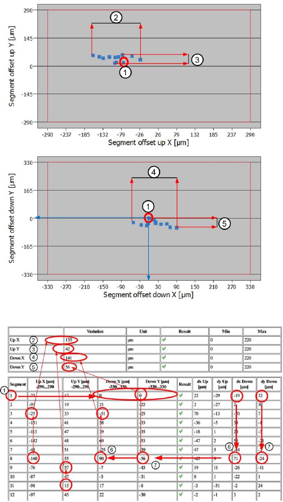
SIPLACE Head V erification User Manual Edition 01/2015 57 Variation Up X [µm ] = -160µm – (-25µm) = | 135µm | The "Variation Up Y" [µm] (3) value i llustrates the m axim um dispersion between the segments for &…
SIPLACE Head Verification
User Manual Edition 01/2015
56
4.9.3 Explanation of Measurement Results Using Results PDF
These results can be seen if you scroll down the "Summary" menu or generate a results PDF!
Figure 37: Result PDF for segment offset up and down_1
Figure 38: Result PDF for segment offset up and down_2
Segment 1 shows that the value for the segment offset "Down X" [µm] and "Down Y" [µm] (1) have
each been determined as 0µm. This is the reference value for the reference segment 1, to which all
other offset values for the other segments refer.
The diagram shows that the offset value for "Down X" [µm] and "Down Y" [µm] for segment 1 are
exactly at the 0µm position (see blue arrow)
The "Variation Up X" [µm] (2) value illustrates the maximum dispersion between the segments for
"Segment offset up" in the X direction.
The "Variation Up X" [µm] is calculated as follows:
Variation Up X [µm] = Up X max [µm] – Up X min [µm]
SIPLACE Head Verification
User Manual Edition 01/2015
57
Variation Up X [µm] = -160µm – (-25µm) = |135µm|
The "Variation Up Y" [µm] (3) value illustrates the maximum dispersion between the segments for
"Segment offset up" in the Y direction.
The "Variation Up Y" [µm] is calculated as follows:
Variation Up Y [µm] = Up Y max [µm] – Up Y min [µm]
Variation Up Y [µm] = 57µm – 15µm = |42µm|
The "Variation Down X" [µm] (4) value illustrates the maximum dispersion between the segments for
"Segment offset down" in the X direction.
The "Variation Down X" [µm] is calculated as follows:
Variation Down X [µm] = Down X max [µm] – Down X min [µm]
Variation Down X [µm] = 90µm – (-51µm) = |141µm|
The "Variation Down Y" [µm] (4) value illustrates the maximum dispersion between the segments for
"Segment offset down" in the Y direction.
The "Variation Down Y" [µm] is calculated as follows:
Variation Down Y [µm] = Down Y max [µm] – Down Y min [µm]
Variation Down Y [µm] = 0µm – (-56µm) = |56µm|
The "Down X" [µm] value for the segments n+1 refers to segment 1. The segment offset actually
measured for segment 1 to the PCB camera is determined with "dx Down" [µm] = -19µm. The value -
19µm is set as the reference value 0µm and results in " Down X" [µm] = 0µm for segment 1.
All other segment offset values "Down X" [µm] are calculated the reference segment 1.
The following formula is applied for this:
Down X [µm] Seg (n) = dx Down [µm] Seg (n) - dx Down [µm] Seg 1
In our example (6) for segment 8, the "Down X" [µm] value for seg. 8 is calculated as follows:
Down X[µm] Seg 8 = 71µm – (-19µm) = 90µm
The "Down Y" [µm] value for the segments n+1 refers to segment 1. The segment offset actually
measured for segment 1 to the PCB camera is determined with "dy Down" [µm] = 32µm. The value
32µm is set as the reference value 0µm and results in " Down Y" [µm] = 0µm for segment 1.
All other segment offset values "Down Y" [µm] are calculated in dependence to the reference segment
1.
The following formula is applied for this:
Down Y [µm] Seg (n) = dy Down [µm] Seg (n) - dy Down [µm] Seg 1
In our example (7) for segment 8, the "Down Y" [µm] value for seg. 8 is calculated as follows:
Down Y [µm] Seg 8 = -24µm – 32µm = -56µm

SIPLACE Head Verification
User Manual Edition 01/2015
58
4.9.4 Meaning of the Results
"Up X [µm]" and "Up Y [µm]" errors at all segments:
1. Check the star zero point correction
"Down X [µm]" and "Down Y [µm]" at all segments:
1. Z axis linear guide loose or defective Check or replace the Z motor
"Up X [µm]" / "Up Y [µm]" / "Down X [µm]" / "Down Y [µm]" at individual segments:
1.
Segment deformed, possibly after a crash Replace segment / DP
2. Linear guide DP/segment worn out Replace the DP / replace the linear guide for segment
4.10 "Filter Disc" Measurement
This measurement is only performed at the CP20A placement head.
This measurement is performed without nozzles on the segments
4.10.1 Explanation of Measurement – Procedure
This measurement checks the filter discs on the segments of the CP20A head.
These filter discs seal the interface between the DP and the nozzle, thereby guaranteeing a reliable
vacuum to the nozzle and protecting the vacuum cycle from contamination.
The machine first places all nozzles in the changer.
Then each segment has blast air of 400mbar applied to it.
This air blast should blow loosely fitted and damaged filter discs off the DP seat.
In addition, any strongly contaminated filter discs will be cleaned (with air blast).
then the segments are examined in order with the component camera, to check whether a filter disc is
fitted or whether it is contaminated.
A digital filter (mask) is placed over the camera image of the filter disc.
An algorithm is used to evaluate the degree to which the digital filter mask recognizes the structures of
the filter disc in the camera image.
A light-dark evaluation is performed. If the camera image is too light, compared to the value set in the
digital filter mask, the filter disc is recognized as missing. There is a threshold for " Filter disc present"
and for "Filter disc missing".
If this measurement was successful and the filter disc is recognized as present, the digital filter mask
is evaluated again and the software searches within the dark filter disc for light-colored pixels. These
light-colored pixels indicate contaminants.If these contaminants exceed a certain number of pixels
(pixel size), the filter disc will be marked as dirty.
The results of these measurements provide feedback about the following sources of errors:
1. Defective filter disks
2. Missing filter discs
3. Defective filter disc seat on the DP