0197787-01_UM_HeadVerification_708_EN.pdf - 第61页
SIPLACE Head V erification User Manual Edition 01/2015 61 2. Segment 1 is m oved downwards with travel profile TP5 [T P5 LIGHT BARRI ER]. The segm ent has the rotar y angle 0°. 3. The component sens or is m onitored duri…

SIPLACE Head Verification
User Manual Edition 01/2015
60
4.10.3 Explanation of Measurement Results Using Results PDF
These results can be seen if you scroll down the "Summary" menu or generate a results PDF!
Figure 40 Results PDF for filter disc
We can see here that the filter discs at segments 4 and 16 have been recognized as faulty. Sadly, the
overview does not reveal the cause of this. The camera image recorded (chapter 6.10.2 legend 4) has
been deleted after generating the PDF.
4.10.4 Meaning of the Results
Error at all filter discs:
1. Check the component camera for contamination
Error at individual filter discs:
1. Filter disc contaminated Replace the filter disc
2. Filter disc broken Replace the filter disc
3. Filter disc missing Insert a new filter disc
4. Filter disc missing at each test Check the filter disc pick-up the DP, to establish whether
there is damage Replace DP
4.11 "Z/DP Positioning" Measurement
The following tools are required for these measurements:
CPP: 12x nozzle type 2069 03094135-01 (vacuum nozzle red, closed)
4.11.1 Explanation of Measurement – Procedure
This measurement checks the deviation between the Z-down light barrier and the component sensor,
in accordance with the angle setting of the segment.
The results of these measurements provide feedback about the following sources of errors:
1. State of linear guide for individual segments
2. State and cleanliness of Z-down light barrier on segment (DP)
3. State of component sensor
Measurement steps:
1. The head is positioned over the height reference run position on the conveyor side.
SIPLACE Head Verification
User Manual Edition 01/2015
61
2. Segment 1 is moved downwards with travel profile TP5 [TP5 LIGHT BARRIER]. The segment
has the rotary angle 0°.
3. The component sensor is monitored during the downwards movement.
As soon as the component sensor is interrupted by the nozzle tip, this value is saved as CS
pos 1 [µm]. This is now the value for the Z axis path, when the nozzle interrupts the
component sensor at segment 1 mit 0°.
4. When the nozzle meets the height reference run position of the conveyor side, the spring is
compressed in the segment and the Z down light barrier is activated by the switching ring.
This position is emitted as the end position signal. The value is saved as Measure 1 [µm] for
segment 1 mit 0°
5. Segment 1 is moved upwards with travel profile TP1.
6. Segment 1 is rotated by 60° 60° absolute
7. Segment 1 is moved downwards again with travel profile TP5 [TP5 LIGHT BARRIER]. The
segment has the rotary angle 60°.
8. The component sensor is monitored during the downwards movement.
As soon as the component sensor is interrupted by the nozzle tip, this value is saved as CS
pos 2 [µm]. This is now the value for the Z axis path, when the nozzle interrupts the
component sensor at segment 1 mit 60°.
9. When the nozzle meets the height reference run position of the conveyor side, the spring is
compressed in the segment and the Z down light barrier is activated by the switching ring.
This position is emitted as the end position signal. The value is saved as Measure 2 [µm] for
segment 1 mit 60°
10. Segment 1 is moved upwards with travel profile TP1.
11. Segment 1 is rotated again by 60° 120° absolute
12. Steps 2-5 are performed again.
13. This is repeated for the other absolute angles 180° / 240° / 300° / 360°.
14. The following measurements are reached for segment 1
Rotary angle 0° Component sensor value CS pos 1 [µm] & Z-Down LS Measure 1 [µm]
Rotary angle 60° Component sensor value CS pos 2 [µm] & Z-Down LS Measure 2 [µm]
Rotary angle 120° Component sensor value CS pos 3 [µm] & Z-Down LS Measure 3 [µm]
Rotary angle 180° Component sensor value CS pos 4 [µm] & Z-Down LS Measure 4 [µm]
Rotary angle 240° Component sensor value CS pos 5 [µm] & Z-Down LS Measure 5 [µm]
Rotary angle 300° Component sensor value CS pos 6 [µm] & Z-Down LS Measure 6 [µm]
You now have measurements for a complete segment rotation, in 60° steps.
15. Steps 2-14 are now performed for all other segments.
SIPLACE Head Verification
User Manual Edition 01/2015
62
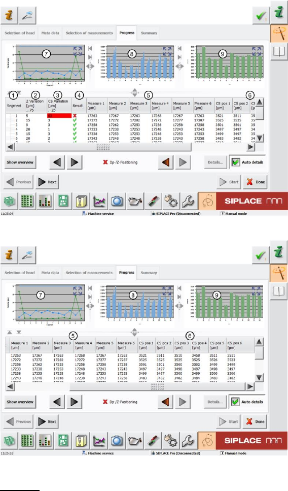
4.11.2 Explanation of Measurement Results in "Progress" Menu
After completion of the measurement, the following results appear in the "Progress" menu:
Figure 41: DP-Z positioning_1 result
Figure 42: DP-Z positioning_2 result
Legend:
1. Segment measured
2. Value determined Z Variation [µm] This value is calculated by finding the difference
between the minimum and maximum Measure 1 – Measure 6 value (end position signal Z-
down light barrier).
Z Variation [µm] = Maximum Measure 1-6 [µm] value – Minimum Measure 1-6 [µm] value
The Z Variation [µm] value shows the Z-down light barrier end position signal variance in
accordance with the rotary angle of the segment.
The "Z Variation [µm]" value must be within a plausible tolerance (in our case 0..75µm).
If the value is outside this tolerance, it is not possible to guarantee accurate placement at
every angle.
3. Value determined CS Variation [µm] This value is calculated by finding the difference
between the minimum and maximum CS pos 1 – CS pos 6 value (interruption of component
sensor).
CS Variation [µm] = Maximum CS pos 1-6 [µm] value – Minimum CS pos 1-6 [µm] value