0197787-01_UM_HeadVerification_708_EN.pdf - 第74页
SIPLACE Head V erification User Manual Edition 01/2015 74 Figure 51 : Function de scription compo nent sensor calibrat ion Diagram legend: 1. Central line for driver be arin g in jaws (slight radi us) 2. Jaw bottom surfa…

SIPLACE Head Verification
User Manual Edition 01/2015
73
The highest value achieved for the "LED gain" was at segment 9 (3). This type of deviation could
indicate that the Z-down light barrier will fail in the near future.
The "Variation 360 [mV]" (8) value is calculated by finding the difference between the "Max value
[mV]" and the "Min value [mV]". In our case this is 4141mV – 3977mV = 164mV
4.13.4 Meaning of the Results
No figures based on experience available!
4.14 "Component Sensor Calibration" Measurement
The following tools are required for these measurements:
CP20P: 20x nozzle type 4235 03098748-01 (calibration nozzle)
4.14.1 Explanation of Measurement – Procedure
The "Component sensor calibration" measurement checks the degree to which the Z height of the
nozzle changes when the Z axis is moved downwards in axis overlapping mode, during the star
rotation and the component sensor is triggered. It checks, when the component sensor switches,
whether the front surface of the nozzle tip triggers the component sensor eccentrically during axis
overlapping. The corner of the front nozzle surface moves slightly downwards during a rotation around
the star in the lower angles (as in the case of jaw stop left and jaw stop right). This can also be
described as a diagonal tilting effect! This Z axis change is recorded during this measurement at the
component sensor.
The results of these measurements provide feedback about the following sources of errors:
1. Slanted component sensor fitting
Measurement steps:
1. Head reference run is performed
2. Segment 1 is rotated with the star into the placement position.
3. The driver bearing is now positioned in the center of the Z axis jaws.
4. The Z axis moves downwards until the jaws are in the center of the raceway cutout and the
component sensor switches.
5. Segment 1 is rotated slowly with the star in the direction of the left stop on the raceway.
6. Once the left stop position is reached, the Z axis begins to step downwards until the corner of
the nozzle front surface triggers the component sensor.
7. The star is now stepped from the left to the right jaw stop.
8. The Z axis is moved in steps until the component sensor is triggered by the front surface of
the nozzle.
9. When the center of the jaws is reached, the smallest value i.e. 0 should be reached.
10. The distance between the lowest Z axis setting (driver in jaw at left or right) and the highest Z
axis setting (driver in center of jaws = 0) at component sensor triggering provides the
Calibration value.
SIPLACE Head Verification
User Manual Edition 01/2015
74
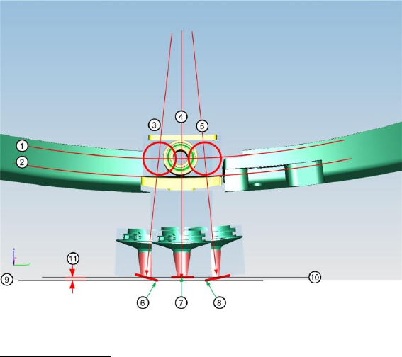
Figure 51: Function description component sensor calibration
Diagram legend:
1. Central line for driver bearing in jaws (slight radius)
2. Jaw bottom surface (slight radius to transition to raceway)
3. Central axis of driver bearing at jaw stop left
4. Central axis of driver bearing in center of jaws
5. Central axis of driver bearing at jaw stop right
6. Corner of nozzle surface, which interrupts component sensor when in jaw stop left position (9)
7. Nozzle tip which interrupts the component sensor in jaw center position (10). This is also
height 0, determined during the reference run and used as a reference point for determining
the Calibration value.
8. Corner of nozzle surface, which interrupts component sensor when in jaw stop left position (9)
9. This is a symbolic illustration of the component sensor beam when the component sensor is
interrupted in the position jaw stop left or jaw stop right. In reality, the component sensor beam
is always at a height of 10, the Z axis must therefore be pulled upwards (negative movement)
so that the corner of the nozzle surface does not yet interrupt the component sensor!
10. Component sensor beam
11. Calibration value
This is the change in Z height when the nozzle surface tilts over the diagonal line during star
rotation and triggers the component sensor "early".
SIPLACE Head Verification
User Manual Edition 01/2015
75
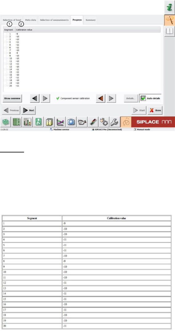
4.14.2 Explanation of Measurement Results in "Progress" Menu
After completion of the measurement, the following results appear in the "Progress2 menu:
Figure 52: Component sensor calibration result
Legend:
1. Segment measured
2. The Calibration value is calculated from the change in Z axis travel path during axis
overlapping (star axis - Z axis) and triggering of the component sensor.
4.14.3 Explanation of Measurement Results Using Results PDF
These results can be seen if you scroll down the "Summary" menu or generate a results PDF!
Figure 53: Results PDF component sensor calibration
See 6.14.2