0197787-01_UM_HeadVerification_708_EN.pdf - 第78页
SIPLACE Head V erification User Manual Edition 01/2015 78 Figure 54 : Segme nt offset up and down resu lt Legend: 1. Segment m easur ed 2. Calculated segm ent offs et for "Up" average Up X [µm] from m easuremen…
SIPLACE Head Verification
User Manual Edition 01/2015
77
7. Segment 1 and the Z axis are moved downwards and the calibration component is placed in
the bag at an angle of 0° (DP/segment angle) and with the corrected offset values Up X [µm]
and Up Y [µm], as a placement position.
8. The PCB camera now moves over the calibration component and once more determines the
four points in the calibration component corners, to find the exact position of the calibration
component in the bag. This provides the offset values Down X [µm] and Down Y [µm], which
describe the eccentricity of the calibration component to the PCB camera center. This value
describes exactly the offset of the segment 1 center at a placement angle of 0°, when
segment 1 is in the placement position. This provides the exact displacement of segment 1 at
a placement angle of 0°, describing how much the Z linear guide has changed the segment
position at the top to the segment position at the bottom.This deviation also describes the
offset of the component camera to the PCB camera for this segment.
9. The calibration component position determined is now used again as actual pickup position for
the following measurement.
10. Segment 1 now picks up at 90°.
11. Segment 1 is moved upwards and can be rotated under the component camera with the help
of the star.
12. The component camera measures the four calibration component structure fiducials to
determine the exact position of the calibration component to the camera center.The offset
values determined here are saved as Up X [µm] and Up Y [µm]. This value now describes
the eccentricity of the calibration component to the camera center.This value provides the
"Segment offset up" for segment 1 at 90°, as we can assume that segment 1 picked up the
calibration component exactly in the center.
13. The star now rotates the segment with the calibration component back into the placement
position.
14. Segment 1 and the Z axis are moved downwards and the calibration component is placed in
the bag at an angle of 90° (DP/segment angle) and with the corrected offset values Up X [µm]
and Up Y [µm], as a placement position.
15. The PCB camera now moves over the calibration component and once more determines the
four points in the calibration component corners, to find the exact position of the calibration
component in the bag. This provides the offset values Down X [µm] and Down Y [µm], which
describe the eccentricity of the calibration component to the PCB camera center. This value
describes exactly the offset of the segment 1 center at a placement angle of 90°, when
segment 1 is in the placement position. This provides the exact displacement of segment 1 at
a placement angle of 90°, describing how much the Z linear guide has changed the segment
position at the top to the segment position at the bottom. This deviation also describes the
offset of the component camera to the PCB camera for this segment.
16. The calibration component position determined is now used again as actual pickup position for
the following measurement.
17. The measurement steps are now repeated for segment 1 with the DP angles 180° and 270°
18. The values determined for segment 1 Down X [µm] and Down Y [µm] are taken as an
absolute 0 for all other calculations of all segment offsets. The "Segment offset down" for
segment 1 is the reference value as all other offsets for all other segments refer to this initial
value.
19. All measurement steps are now performed for the other segments at the angles 0°, 90°, 180°
and 270°.
20. The calibration component stays in its position at 0° for the entire measurement and does not
change its angle!The measured angles refer to the angles of the DP at which the calibration
component is picked up from the DP.
4.15.2 Explanation of Measurement Results in "Progress" Menu
After completion of the measurement, the following results appear in the "Progress" menu:
SIPLACE Head Verification
User Manual Edition 01/2015
78
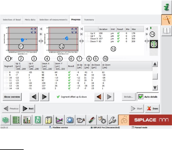
Figure 54: Segment offset up and down result
Legend:
1. Segment measured
2. Calculated segment offset for "Up" average Up X [µm] from measurement at angles 0°, 90°,
180° and 270°. This deviation is determined with the value dx Up [µm] (7), as the actual
segment offset measured to the component camera center. The segment offset "Up" value Up
X [µm] is calculated from the offset average values at the angles 0°, 90°, 180° and 270°,
between the component and PCB camera.
The segment offset values Up X [µm] determined must always be in a certain tolerance range
(in our example -290..290µm). This value defines a permissible segment offset within the
construction and production tolerances, which can still be compensated by the software. If the
segment offset values are outside the tolerances, we can assume that the segment has been
mechanically deformed, so that it has been bent and is no longer suitable for accurate
placement.
3. Calculated segment offset for "Up" average Up Y [µm] from measurement at angles 0°, 90°,
180° and 270°. This deviation is determined with the value dy Up [µm] (8), as the actual
segment offset measured to the component camera center. The segment offset "Up" value Up
Y [µm] is calculated from the offset average values at the angles 0°, 90°, 180° and 270°,
between the component and PCB camera.
The segment offset values Up Y [µm] determined must always be in a certain tolerance range
(in our example -290..290µm). This value defines a permissible segment offset within the
construction and production tolerances, which can still be compensated by the software. If the
segment offset values are outside the tolerances, we can assume that the segment has been
mechanically deformed, so that it has been bent and is no longer suitable for accurate
placement.
4. Calculated segment offset for "Down" average Down X [µm] from measurement at angles 0°,
90°, 180° and 270°. This value is calculated from the actual segment offset "Down" average
value dx Down [µm] for this segment. This offset is illustrated in the value dx Down [µm] (9).
The segment offset values Down X [µm] determined must always be in a certain tolerance
range (in our example -330..330µm). This value defines a permissible segment offset within
the construction and production tolerances, which can still be compensated by the software. If
the segment offset values are outside the tolerances, we can assume that the segment has
been mechanically deformed, so that it has been bent and is no longer suitable for accurate
placement.
The Down X [µm] value for segment 1 is used as a reference value for all other segments
and is therefore always set to 0.
SIPLACE Head Verification
User Manual Edition 01/2015
79
As the "Segment offset down" for segment 1 is the reference value for all other segment
offsets, the actual segment offset value dx Down [µm] is set to 0 for "Down X [µm] = 0"!
The following formula is used for the relationship of all other segments:
Down X [µm] Seg (n) = dx Down [µm] Seg (n) - dx Down [µm] Seg 1
5. Calculated segment offset for "Down" average Down Y [µm] from measurement at angles 0°,
90°, 180° and 270°. This value is calculated from the actual segment offset "Down" average
value dy Down [µm] for this segment. This offset is illustrated in the value dy Down [µm]
(10).
The segment offset values Down Y [µm] determined must always be in a certain tolerance
range (in our example -330..330µm). This value defines a permissible segment offset within
the construction and production tolerances, which can still be compensated by the software. If
the segment offset values are outside the tolerances, we can assume that the segment has
been mechanically deformed, so that it has been bent and is no longer suitable for accurate
placement.
The Down Y [µm] value for segment 1 is used as a reference value for all other segments
and is therefore always set to 0.
As the "Segment offset down" for segment 1 is the reference value for all other segment
offsets, the actual segment offset value dx Down [µm] is set to 0 for "Down X [µm] = 0"!
The following formula is used for the relationship of all other segments:
Down Y [µm] Seg (n) = dy Down [µm] Seg (n) - dy Down [µm] Seg 1
6. Results display (OK green tick / NOK red X)
7. Actual segment offset average dx Up [µm] for relevant segment to component camera center
at an angle of 0°, 90°, 180° and 270°.
8. Actual segment offset average dy Up [µm] for relevant segment to component camera center
at an angle of 0°, 90°, 180° and 270°.
9. Actual segment offset average dx Down [µm] for relevant segment to component camera
center at an angle of 0°, 90°, 180° and 270°.
10. Actual segment offset average dy Down [µm] for relevant segment to component camera
center at an angle of 0°, 90°, 180° and 270°.
11. Diagram for illustration of segment offset values "up" with the following values:
Axis of abscissas (X axis) Segment offset up X [µm]
Axis of ordinate (Y axis) Segment offset up Y [µm]
Red border Min and max tolerances (in our case -290..290µm)
Use the button to zoom in on the diagram.
12. Diagram for illustration of segment offset values "down" with the following values:
Axis of abscissas (X axis) Segment offset down X [µm]
Axis of ordinate (Y axis) Segment offset down Y [µm]
Red border Min and max tolerances (in our case -330..330µm)
Use the button to zoom in on the diagram.
13. The following values are displayed in this screen:
a. Dispersion Up X This value is determined by finding the difference between
the lowest value for "Up X" [µm] (2) and the highest values for "Up X" [µm] (2). This
difference must be within a plausible tolerance (in this case 0..220µm).
b. Dispersion Up Y This value is determined by finding the difference between
the lowest value for "Up Y" [µm] (3) and the highest values for "Up Y" [µm] (3). This
difference must be within a plausible tolerance (in this case 0..220µm).
c. Dispersion Down X This value is determined by finding the difference
between the lowest value for "Down X" [µm] (4) and the highest values for "Down X"
[µm] (4). This difference must be within a plausible tolerance (in this case 0..220µm).
d. Dispersion Down Y This value is determined by finding the difference
between the lowest value for "Down Y" [µm] (5) and the highest values for "Down Y"
[µm] (5). This difference must be within a plausible tolerance (in this case 0..220µm).
e. Results display (OK green tick / NOK red X)