0197787-01_UM_HeadVerification_708_EN.pdf - 第79页
SIPLACE Head V erification User Manual Edition 01/2015 79 As the "Segment off set down" for segm ent 1 is the ref erence value for a ll other segm ent offsets, the actual segm ent offset value dx Down [µm ] is …
SIPLACE Head Verification
User Manual Edition 01/2015
78
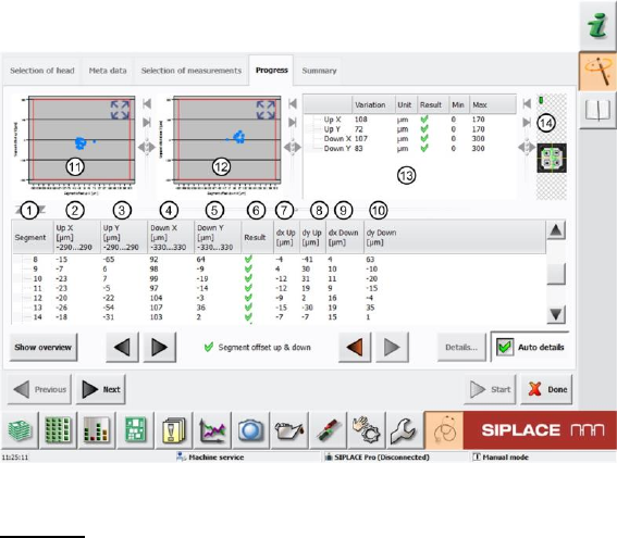
Figure 54: Segment offset up and down result
Legend:
1. Segment measured
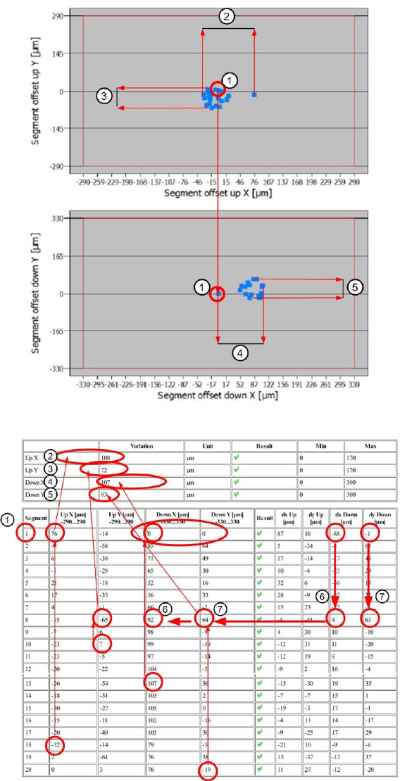
2. Calculated segment offset for "Up" average Up X [µm] from measurement at angles 0°, 90°,
180° and 270°. This deviation is determined with the value dx Up [µm] (7), as the actual
segment offset measured to the component camera center. The segment offset "Up" value Up
X [µm] is calculated from the offset average values at the angles 0°, 90°, 180° and 270°,
between the component and PCB camera.
The segment offset values Up X [µm] determined must always be in a certain tolerance range
(in our example -290..290µm). This value defines a permissible segment offset within the
construction and production tolerances, which can still be compensated by the software. If the
segment offset values are outside the tolerances, we can assume that the segment has been
mechanically deformed, so that it has been bent and is no longer suitable for accurate
placement.
3. Calculated segment offset for "Up" average Up Y [µm] from measurement at angles 0°, 90°,
180° and 270°. This deviation is determined with the value dy Up [µm] (8), as the actual
segment offset measured to the component camera center. The segment offset "Up" value Up
Y [µm] is calculated from the offset average values at the angles 0°, 90°, 180° and 270°,
between the component and PCB camera.
The segment offset values Up Y [µm] determined must always be in a certain tolerance range
(in our example -290..290µm). This value defines a permissible segment offset within the
construction and production tolerances, which can still be compensated by the software. If the
segment offset values are outside the tolerances, we can assume that the segment has been
mechanically deformed, so that it has been bent and is no longer suitable for accurate
placement.
4. Calculated segment offset for "Down" average Down X [µm] from measurement at angles 0°,
90°, 180° and 270°. This value is calculated from the actual segment offset "Down" average
value dx Down [µm] for this segment. This offset is illustrated in the value dx Down [µm] (9).
The segment offset values Down X [µm] determined must always be in a certain tolerance
range (in our example -330..330µm). This value defines a permissible segment offset within
the construction and production tolerances, which can still be compensated by the software. If
the segment offset values are outside the tolerances, we can assume that the segment has
been mechanically deformed, so that it has been bent and is no longer suitable for accurate
placement.
The Down X [µm] value for segment 1 is used as a reference value for all other segments
and is therefore always set to 0.
SIPLACE Head Verification
User Manual Edition 01/2015
79
As the "Segment offset down" for segment 1 is the reference value for all other segment
offsets, the actual segment offset value dx Down [µm] is set to 0 for "Down X [µm] = 0"!
The following formula is used for the relationship of all other segments:
Down X [µm] Seg (n) = dx Down [µm] Seg (n) - dx Down [µm] Seg 1
5. Calculated segment offset for "Down" average Down Y [µm] from measurement at angles 0°,
90°, 180° and 270°. This value is calculated from the actual segment offset "Down" average
value dy Down [µm] for this segment. This offset is illustrated in the value dy Down [µm]
(10).
The segment offset values Down Y [µm] determined must always be in a certain tolerance
range (in our example -330..330µm). This value defines a permissible segment offset within
the construction and production tolerances, which can still be compensated by the software. If
the segment offset values are outside the tolerances, we can assume that the segment has
been mechanically deformed, so that it has been bent and is no longer suitable for accurate
placement.
The Down Y [µm] value for segment 1 is used as a reference value for all other segments
and is therefore always set to 0.
As the "Segment offset down" for segment 1 is the reference value for all other segment
offsets, the actual segment offset value dx Down [µm] is set to 0 for "Down X [µm] = 0"!
The following formula is used for the relationship of all other segments:
Down Y [µm] Seg (n) = dy Down [µm] Seg (n) - dy Down [µm] Seg 1
6. Results display (OK green tick / NOK red X)
7. Actual segment offset average dx Up [µm] for relevant segment to component camera center
at an angle of 0°, 90°, 180° and 270°.
8. Actual segment offset average dy Up [µm] for relevant segment to component camera center
at an angle of 0°, 90°, 180° and 270°.
9. Actual segment offset average dx Down [µm] for relevant segment to component camera
center at an angle of 0°, 90°, 180° and 270°.
10. Actual segment offset average dy Down [µm] for relevant segment to component camera
center at an angle of 0°, 90°, 180° and 270°.
11. Diagram for illustration of segment offset values "up" with the following values:
Axis of abscissas (X axis) Segment offset up X [µm]
Axis of ordinate (Y axis) Segment offset up Y [µm]
Red border Min and max tolerances (in our case -290..290µm)
Use the button to zoom in on the diagram.
12. Diagram for illustration of segment offset values "down" with the following values:
Axis of abscissas (X axis) Segment offset down X [µm]
Axis of ordinate (Y axis) Segment offset down Y [µm]
Red border Min and max tolerances (in our case -330..330µm)
Use the button to zoom in on the diagram.
13. The following values are displayed in this screen:
a. Dispersion Up X This value is determined by finding the difference between
the lowest value for "Up X" [µm] (2) and the highest values for "Up X" [µm] (2). This
difference must be within a plausible tolerance (in this case 0..220µm).
b. Dispersion Up Y This value is determined by finding the difference between
the lowest value for "Up Y" [µm] (3) and the highest values for "Up Y" [µm] (3). This
difference must be within a plausible tolerance (in this case 0..220µm).
c. Dispersion Down X This value is determined by finding the difference
between the lowest value for "Down X" [µm] (4) and the highest values for "Down X"
[µm] (4). This difference must be within a plausible tolerance (in this case 0..220µm).
d. Dispersion Down Y This value is determined by finding the difference
between the lowest value for "Down Y" [µm] (5) and the highest values for "Down Y"
[µm] (5). This difference must be within a plausible tolerance (in this case 0..220µm).
e. Results display (OK green tick / NOK red X)
SIPLACE Head Verification
User Manual Edition 01/2015
80
4.15.3 Explanation of Measurement Results Using Results PDF
These results can be seen if you scroll down the "Summary" menu or generate a results PDF!
Figure 55: Result PDF for segment offset up and down_1
Figure 56: Result PDF for segment offset up and down_2
Segment 1 shows that the value for the segment offset "Down X" [µm] and "Down Y" [µm] (1) have
each been determined as 0µm. This is the reference value for the reference segment 1, to which all
other offset values for the other segments refer.
The diagram shows that the offset value for "Down X" [µm] and "Down Y" [µm] for segment 1 are
exactly at the 0µm position (see blue arrow)