0197787-01_UM_HeadVerification_708_EN.pdf - 第81页
SIPLACE Head V erification User Manual Edition 01/2015 81 The "Variation Up X" [µm] (2) value i llustrates the m axim um dispersion between the segm ents for "Segment off set up" in the X direction. T…
SIPLACE Head Verification
User Manual Edition 01/2015
80
4.15.3 Explanation of Measurement Results Using Results PDF
These results can be seen if you scroll down the "Summary" menu or generate a results PDF!
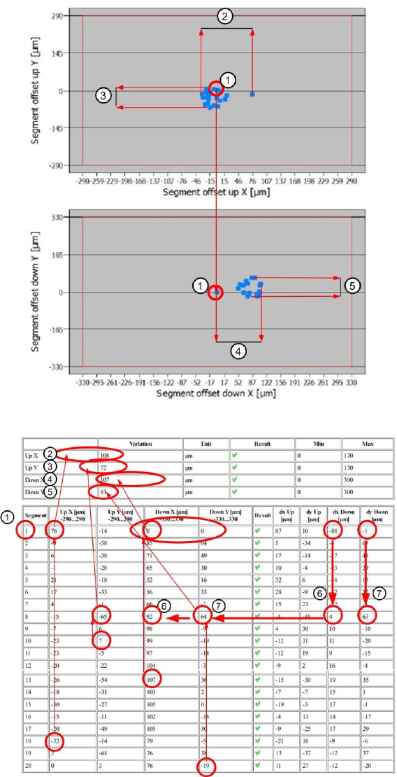
Figure 55: Result PDF for segment offset up and down_1
Figure 56: Result PDF for segment offset up and down_2
Segment 1 shows that the value for the segment offset "Down X" [µm] and "Down Y" [µm] (1) have
each been determined as 0µm. This is the reference value for the reference segment 1, to which all
other offset values for the other segments refer.
The diagram shows that the offset value for "Down X" [µm] and "Down Y" [µm] for segment 1 are
exactly at the 0µm position (see blue arrow)

SIPLACE Head Verification
User Manual Edition 01/2015
81
The "Variation Up X" [µm] (2) value illustrates the maximum dispersion between the segments for
"Segment offset up" in the X direction.
The "Variation Up X" [µm] is calculated as follows:
Variation Up X [µm] = Up X max [µm] – Up X min [µm]
Variation Up X [µm] = 76µm – (-32µm) = |108µm|
The "Variation Up Y" [µm] (3) value illustrates the maximum dispersion between the segments for
"Segment offset up" in the Y direction.
The "Variation Up Y" [µm] is calculated as follows:
Variation Up Y [µm] = Up Y max [µm] – Up Y min [µm]
Variation Up Y[µm] = 7µm – (-65µm) = |72µm|
The "Variation Down X" [µm] (4) value illustrates the maximum dispersion between the segments for
"Segment offset down" in the X direction.
The "Variation Down X" [µm] is calculated as follows:
Variation Down X [µm] = Down X max [µm] – Down X min [µm]
Variation Down X [µm] = 107µm – 0µm = |107µm|
The "Variation Down Y" [µm] (4) value illustrates the maximum dispersion between the segments for
"Segment offset down" in the Y direction.
The "Variation Down Y" [µm] is calculated as follows:
Variation Down Y [µm] = Down Y max [µm] – Down Y min [µm]
Variation Down Y [µm] = 64µm – (-19µm) = |83µm|
The "Down X" [µm] value for the segments n+1 refers to segment 1. The segment offset actually
measured for segment 1 to the PCB camera is determined with "dx Down" [µm] = -19µm. The value -
19µm is set as the reference value 0µm and results in " Down X" [µm] = 0µm for segment 1.
All other segment offset values "Down X" [µm] are calculated in dependence to the reference segment
1.
The following formula is applied for this:
Down X [µm] Seg (n) = dx Down [µm] Seg (n) - dx Down [µm] Seg 1
In our example (6) for segment 8, the "Down X" [µm] value for seg. 8 is calculated as follows:
Down X[µm] Seg 8 = 4µm – (-88µm) = 92µm
The "Down Y" [µm] value for the segments n+1 refers to segment 1. The segment offset actually
measured for segment 1 to the PCB camera is determined with "dy Down" [µm] = 32µm. The value
32µm is set as the reference value 0µm and results in " Down Y" [µm] = 0µm for segment 1.
All other segment offset values "Down Y" [µm] are calculated in dependence to the reference segment
1.
The following formula is applied for this:
Down Y [µm] Seg (n) = dy Down [µm] Seg (n) - dy Down [µm] Seg 1
In our example (7) for segment 8, the "Down Y" [µm] value for seg. 8 is calculated as follows:
Down Y [µm] Seg 8 = 63µm – (-1µm) = 64µm

SIPLACE Head Verification
User Manual Edition 01/2015
82
Meaning of the Results
"Up X [µm]" and "Up Y [µm]" errors at all segments:
1. Check the star zero point correction
"Down X [µm]" and "Down Y [µm]" at all segments:
1. Z axis linear guide loose or defective Check or replace the Z motor
"Up X [µm]" / "Up Y [µm]" / "Down X [µm]" / "Down Y [µm]" at individual segments:
1.
Segment deformed, possibly after a crash Replace segment / DP
2. Linear guide DP/segment worn out Replace the DP / replace the linear guide for segment