SIPLACE TX V2 micron 设备性能参数_DMS - 第8页
8 Placement heads SIPLACE SpeedStar (C&P20 M3) SIPLACE SpeedS t ar (C&P20 M3) With component camera type 48 (St andard) With compo nent camera type 4 9 (Optional) Component range a a) Please note that the placeab…

7
Machine performance
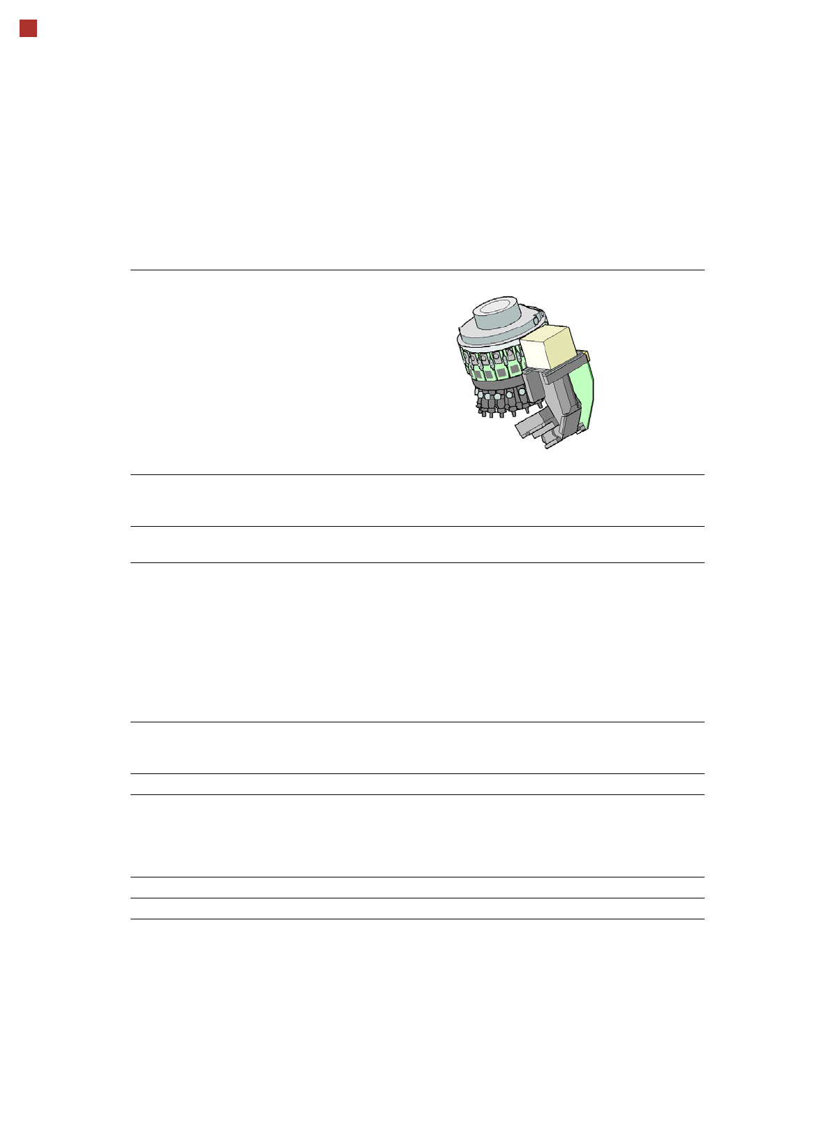
Placement head types SIPLACE SpeedStar (C&P20 M3)
SIPLACE MultiStar (CPP M)
Placement performance
The placement performance is influenced by the different head combinations and head positions, plus the conveyor
configurations. Individual options and customized applications also influence the placement performance. On request,
ASM can calculate the actual performance of your product on your machine configuration.
IPC value [components/h]
Conducted with 0402 components, in accordance with the layout of the IPC 9850 standard of Association Connecting
Electronics Industries.
SIPLACE benchmark value [components/h]
The SIPLACE benchmark value is measured during the machine acceptance tests. It corresponds to the conditions set
out in the ASM scope of service and supply.
SIPLACE TX2 m placement
machine
Placement area IPC value Benchmark
value
Standard C&P20 M3 / C&P20 M3 72,300 85,500
C&P20 M3 / CPP M_L 57,800 66,600
CPP M_L / CPP M_L 43,300 47,700
Placement accuracy 20 µm (3) C&P20 M3 / C&P20 M3 64,000 76,000
C&P20 M3 / CPP M_L 54,000 62,500
CPP M_L / CPP M_L 38,000 46,000
Placement accuracy 15 µm (3) C&P20 M3 / C&P20 M3 ---
a
a) IPC value is not possible, as the IPC PCB is larger than 250 mm x 100 mm,
70,000
SIPLACE TX2i m placement
machine
Placement area IPC value Benchmark
value
Standard C&P20 M3 / C&P20 M3 78,000 96,000
Placement accuracy 20 µm (3) C&P20 M3 / C&P20 M3 70,000 83,000
Placement accuracy 15 µm (3) C&P20 M3 / C&P20 M3 ---
a
75,000
SIPLACE TX2i m 4 mm placement
machine
Placement area IPC value Benchmark
value
Standard C&P20 M3 / C&P20 M3 76,000 93,000
Placement accuracy 20 µm (3) C&P20 M3 / C&P20 M3 68,000 81,000
Placement accuracy 15 µm (3) C&P20 M3 / C&P20 M3 ---
a
73,000
8
Placement heads
SIPLACE SpeedStar (C&P20 M3)
SIPLACE SpeedStar (C&P20 M3)
With component camera
type 48 (Standard)
With component
camera type 49
(Optional)
Component range
a
a) Please note that the placeable component range is also affected by the pad geometry, the customer-
specific standards, the component packaging tolerances and the component tolerances.
0.12 mm x 0.12 (0201 metric) to 2220, Melf, SOT, SOD, Bare-
Die, Flip-Chip
Component spec.
Max. height
Max. height
b
Min. lead pitch
Min. lead width
Min. ball pitch
Min. ball diameter
Min. dimensions
Max. dimensions
Max. weight
b) The maximum component height of 4 mm is only possible with the machine type
SIPLACE TX2i m 4 mm.
2 mm
4 mm
70 µm
30 µm
100 µm
50 µm
120 µm x 120 µm
8.2 mm x 8.2 mm
1 g
2 mm
c
4 mm
c
50 µm
25 µm
50 µm
25 µm
80 µm x 80 µm
8.2 mm x 8.2 mm
1 g
c) Due to the small focus area of ±0.3 mm, this camera is only recommended if its specific camera resolu-
tion is required for the components. The requirements for component camera type 49 are achieved in
the ±0.3mm range. The component camera type 49 achieves the performance rating of component cam-
era type 48 in the ±0.6mm range. The nozzle length must be adjusted in accordance with the focus area
and component thickness.
Set-down force 1.3 N ± 0.5 N (default value)
0.5 N to 4.5 N
Touchless Placement
Nozzle types 60xx 60xx
X/Y accuracy
d
Standard
With "accuracy class"
e
d) The benchmark and accuracy values are measured during the machine acceptance tests and corre-
spond to the conditions set out in the ASM scope of service and supply.
e) Setting the accuracy class in the SIPLACE Pro Component Shape Editor or Placement Position Editor.
15 µm only possible with PCBs up to a size of 250 mm x 100 mm.
± 25 µm/3
± 20 µm/3
± 15 µm/3
± 25 µm/3
± 20 µm/3
± 15 µm/3
Angular accuracy ± 0.25° / 3 ± 0.25° / 3
Illumination levels 5 5

9
Placement heads
SIPLACE MultiStar (CPP M)
SIPLACE MultiStar (CPP M)
With component camera type 45
(Standard)
with component camera
type 30
(Optional)
Component range
a
a) Please note that the placeable component range is also affected by the pad geometry, the customer-specific
standards, the component packaging tolerances and the component tolerances.
01005 to 15 mm x 15 mm 01005 to 27 mm x 27 mm
Component specifications
Max. height
b
Min. lead pitch
Min. lead width
Min. ball pitch
Min. ball diameter
Min. dimensions
Max. dimensions
Max. weight
b) CPP M head: in low installation position
6.0 mm
250 µm / 120 µm
c
50 µm
140 µm
70 µm
0.11 mm x 0.11 mm
15 mm x 15 mm
4 g
c) Only possible for components which are within the focal range of the camera of ± 1.3 mm.
6.0 mm
250 µm
100 µm
d
/ 200 µm
e
250 µm
e
/ 350 µm
f
140 µm
e
/ 200 µm
f
0.4 mm x 0.2 mm
27 mm x 27 mm
4 g
d) For components < 18 mm x 18 mm.
e) For components ≥ 18 mm x18 mm.
Programmable set-down force 1.0 - 15 N 1.0 - 15 N
Nozzle types 20xx, 28xx 20xx, 28xx
X/Y accuracy
f
With "accuracy class"
g
Without "accuracy class"
f) The benchmark and accuracy values are measured during the machine acceptance tests and correspond
to the conditions set out in the ASM scope of service and supply.
g) Setting the accuracy class in the SIPLACE Pro Component Shape Editor or Placement Position Editor.
± 20 µm/3
± 25 µm/3
± 20 µm/3
± 25 µm/3
Angular accuracy ± 0.18° / 3 ± 0.18° / 3
Illumination levels 5 5
Standard functions High-resolution camera, vacuum sensor, force measurement,
component sensor, integrated turning station per segment, PCB
warpage check, individual image of each component