00194482-02_AI_NozzleChanger_X_605_DE+EN.pdf - 第40页
Assembly instructions Nozzle changer SIPLACE X-Series / D3 11/2011 Edition 40 2 : Fix the cable using cable clip s. 2 For single gantry placement area s, the cable must be fixed at locations 2 and 4 so that it cannot be …

Assembly instructions Nozzle changer SIPLACE X-Series / D3
11/2011 Edition
39
2.3 Connecting the nozzle changers to the CAN Nodes
The main task of the CAN node is to control the tape cutter. The cables are run as a default in the
component feed device and connected to the CAN node option. The connectors can therefore be
found on the back of the component feed device, above the empty tape duct. 2
2
2
Although some component feed devices already have the cables for the CAN node module ready,
the old version of the cutter control is still used. In this case, you either need to convert to the CAN
node module or use the 1 wire hub. 2
– Mixed configurations in the same machine are not possible.
– Old cutter control board: [03006411-xx]
– New cutter control board for CAN node module [03052927-xx]
– From machine number B752 the component feed device has been converted fully to the
CAN node option.
– For conversion to the CAN nodes option, please contact your SIPLACE Service team.
2.4 Installing the one-wire hub (all nozzle changers)
The 1 wire hub is used to control the following options up until SW605: 2
– Verify sensors for reject bin
– Nozzle changers for C&P20, C&P6 and C&P12
2
2
If one of these two options is already fitted at the relevant location, an additional 1 wire hub is not
required. 2
2
: Switch the placement system off at the main switch.
2
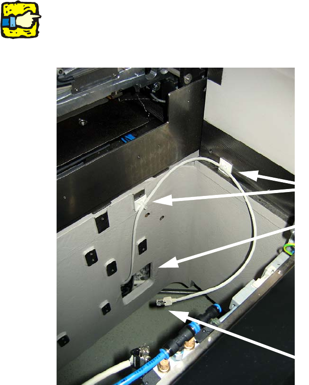
: Pull the patch cable
(item no. 03041628-xx for location 1 + 3 / item no. 03041627-xx for location 2 + 4)
out of the opening in the machine frame (see photograph below).
2
2
Do not run the cable together with the wiring harness in order to avoid electrical interference. 2
Assembly instructions Nozzle changer SIPLACE X-Series / D3
11/2011 Edition
40
2
: Fix the cable using cable clips.
2
For single gantry placement areas, the cable must be fixed at locations 2 and 4 so that it cannot
be damaged by the component trolley docking unit. 2
2
2
2
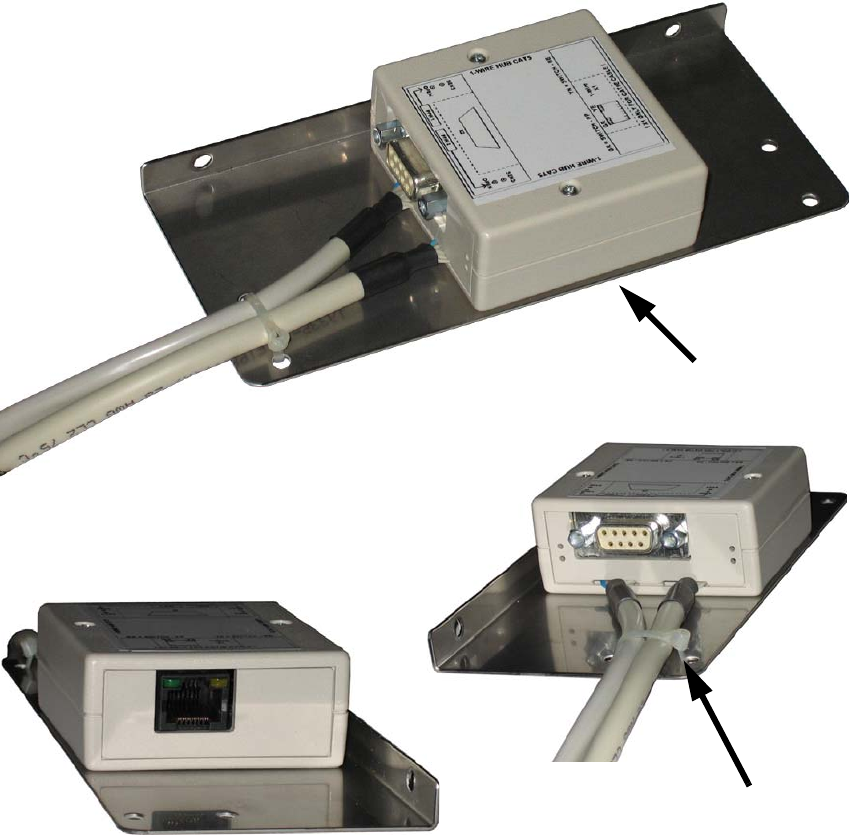
: Screw the one-wire hub to the assembly bracket (2x mushroom-head self-tapping screw, Torx
D2.5x6, item no.: 03009465-xx).
Fix the connecting cables using cable ties.
Opening in the machine frame
Cable clips
Connector to the HUB
Assembly instructions Nozzle changer SIPLACE X-Series / D3
11/2011 Edition
41
2
2
: Use the assembly bracket and two screws to fit the HUB and then attach the connecting cable
(see photographs below).
: Remove the blanking plug from the compressed air hose and fit the reducer
(reducer for nozzle changer C&P20 consisting of:
03021003-xx Hose connector RTU-PK-3/4
03032029-xx Hose HT PUN-6 L=40 mm).
2 screws on the underside
Cable ties