00194482-02_AI_NozzleChanger_X_605_DE+EN.pdf - 第42页
Assembly instructions Nozzle changer SIPLACE X-Series / D3 11/2011 Edition 42 2 2 Connecting cable 2 screws (DIN 6912-M4 x 8-8.8, item no.: 00095106- xx)
Assembly instructions Nozzle changer SIPLACE X-Series / D3
11/2011 Edition
41
2
2
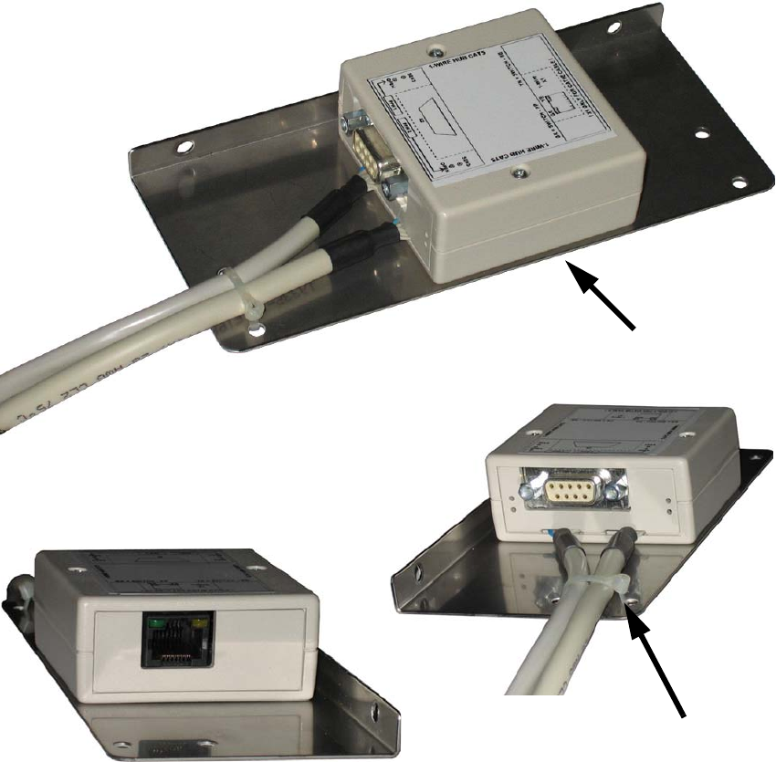
: Use the assembly bracket and two screws to fit the HUB and then attach the connecting cable
(see photographs below).
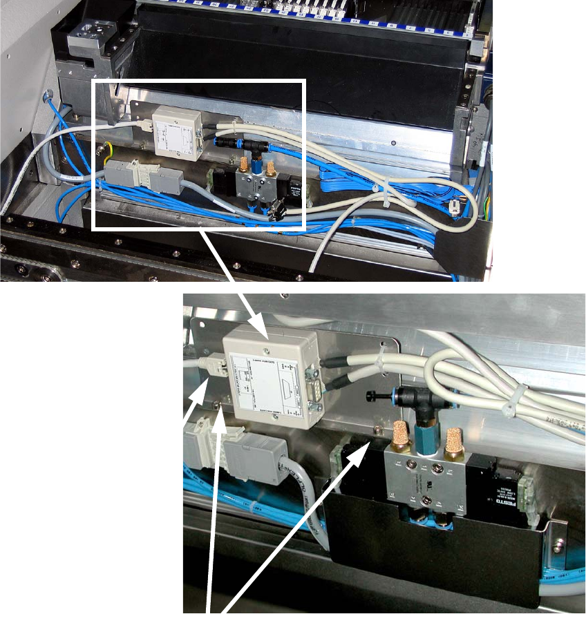
: Remove the blanking plug from the compressed air hose and fit the reducer
(reducer for nozzle changer C&P20 consisting of:
03021003-xx Hose connector RTU-PK-3/4
03032029-xx Hose HT PUN-6 L=40 mm).
2 screws on the underside
Cable ties
Assembly instructions Nozzle changer SIPLACE X-Series / D3
11/2011 Edition
42
2
2
Connecting cable
2 screws
(DIN 6912-M4 x 8-8.8, item no.: 00095106-xx)
Assembly instructions Nozzle changer SIPLACE X-Series / D3
11/2011 Edition
43
2.5 Setting the height
2.5.1 Setting the height of the nozzle changer contact surface
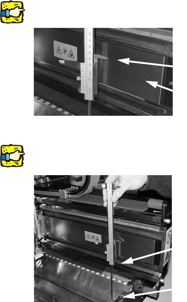
: Push the placement head inwards for the measurement on the outer side.
: Move the gantry so that the placement head is roughly at the subsequent nozzle changer po-
sition (photographs C&P 6/12).
2
Make sure that, in the subsequent measurement, the tip of the caliper gauge does not touch the
magnetic rail for the internal measurement since it could damage the rail. 2
2
: Place the caliper gauge on the top edge of the lower X-axis linear guide and measure up to the
nozzle changer contact surface.
2
Hold the caliper gauge vertically. 2
2
2
Tip of the caliper gauge
Magnetic surface
Support the lower end of the
caliper gauge here
Measure up to the nozzle
changer contact surface.