00194482-02_AI_NozzleChanger_X_605_DE+EN.pdf - 第47页
Assembly instructions Nozzle changer SIPLACE X-Series / D3 11/2011 Edition 47 2.5.2 Setting the height of the nozzle ejector : Push the placement head outwards for the measureme nt. 2 : Place the caliper gauge on the to …
Assembly instructions Nozzle changer SIPLACE X-Series / D3
11/2011 Edition
46
: Screw the contact surfaces on again with the spacers beneath them.
2
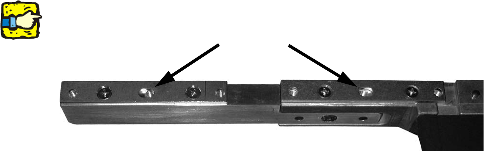
The slots between the fixing holes/screws are seated off-centre on the holes. 2
2
2
: Check that the distance is now correct (150.0 +/- 0.2 mm).
If it is not, then adjust the distance using the spacers.
2
2
2
2
2
2
2
2
2
2
2
2
2
2
2
2
2
2
Slots
Nozzle changer second row
Assembly instructions Nozzle changer SIPLACE X-Series / D3
11/2011 Edition
47
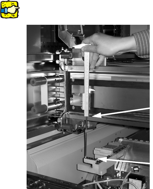
2.5.2 Setting the height of the nozzle ejector
: Push the placement head outwards for the measurement.
2
: Place the caliper gauge on the top edge of the nozzle take-off device and measure the distance
to the bottom edge of the lower X-axis linear guide.
2
Hold the caliper gauge vertically 2
2
2
2
: Set the distance for all placement heads to 139.0 mm +/- 0.2 mm.
If the distance is correct, continue by installing the nozzle changer in the placement machine.
2
2
2
Support the bottom edge of the
caliper gauge on the take-off
device
Support the bottom edge of the
caliper gauge on the linear guide
Assembly instructions Nozzle changer SIPLACE X-Series / D3
11/2011 Edition
48
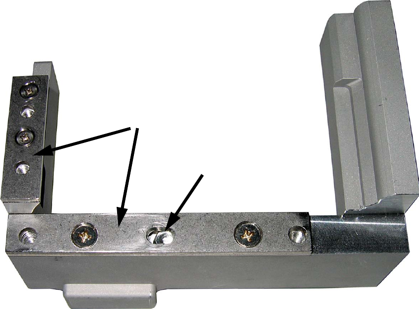
: If the distance is too high, adjust the distance using the spacers for nozzle ejector
(item no: 03039514-xx).
2
2
2
2
Longitudinal hole
Spacers