00194482-02_AI_NozzleChanger_X_605_DE+EN.pdf - 第50页
Assembly instructions Nozzle changer SIPLACE X-Series / D3 11/2011 Edition 50 : Attach the compressed air hose with the reducer at the mag net valve of the componen t trolley docking unit (pressure: 4.5 bar) . (Reducer f…
Assembly instructions Nozzle changer SIPLACE X-Series / D3
11/2011 Edition
49
2.6 Nozzle changer, C&P20 placement head
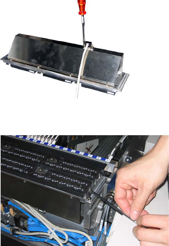
: Plug the connecting cable labelled nozzle changer 1 to the nozzle changer and screw it tight.
2
2
: Screw on the nozzle changer using 4 screws DIN912-M5 x 14-8.8
(item no.: 00306631-xx).
2
2
2
Assembly instructions Nozzle changer SIPLACE X-Series / D3
11/2011 Edition
50
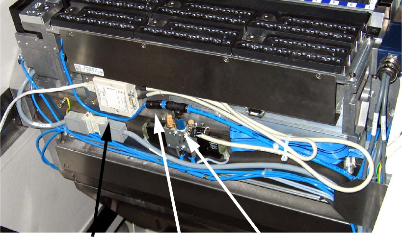
: Attach the compressed air hose with the reducer at the magnet valve of the component trolley
docking unit (pressure: 4.5 bar).
(Reducer for nozzle changer C&P20 consisting of:
03021003-xx Hose connector RTU-PK-3/4
03032029-xx Hose HT PUN-6 L=40 mm).
2
2
: Secure all the cables and hoses using cable ties.
2
2
2
2
2
2
2
2
2
2
2
Compressed air hose
Reducer
Magnet valve
Assembly instructions Nozzle changer SIPLACE X-Series / D3
11/2011 Edition
51
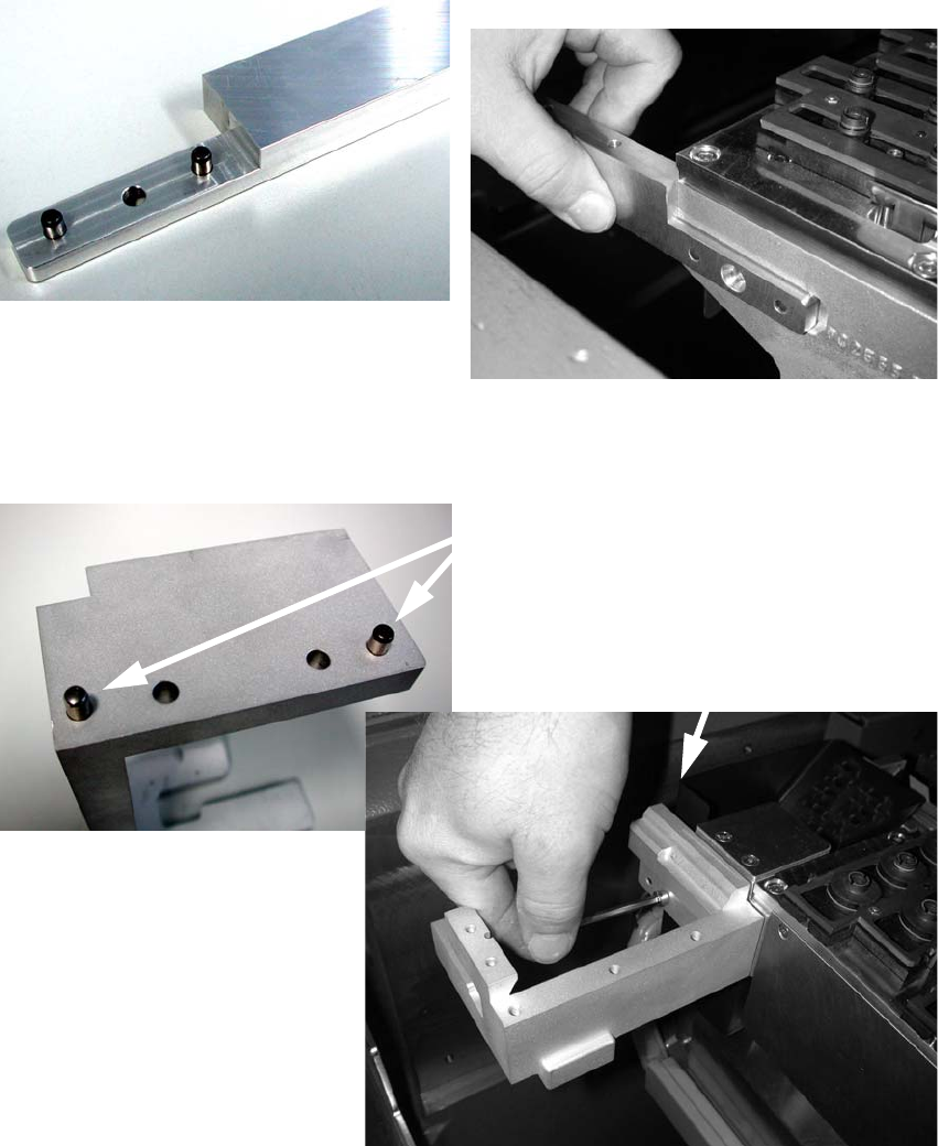
Fitting the second row of C&P20 nozzle changers 2
: Fit the mounts for the second row of nozzle changers and check the height as described in sec-
tion 1.3.1 Setting the height of the nozzle changer contact surface.
: Tap the dowel pins (DIN 6325 - 5m6 x 14-St, item no.: 00323142-xx) into the relevant holes in
the mount and screw the mount in place as shown (screws DIN 7991-M5 x 12-8.8, item no.:
00306624-xx).
2
: Tap the pins into the relevant holes in the nozzle ejector mount and screw the mount on as
shown.
2
Pins
DIN 6325 - 5m5 x 16-St, item no.: 00619866-xx
Screws
DIN912-M5 x 16-8.8, item no.: 00845044-xx