00194482-02_AI_NozzleChanger_X_605_DE+EN.pdf - 第53页
Assembly instructions Nozzle changer SIPLACE X-Series / D3 11/2011 Edition 53 2.7 Nozzle changer , C&P 6/12 placement head : Switch the placement system off at the main switch. : T ap the pins into the appropriate ho…
Assembly instructions Nozzle changer SIPLACE X-Series / D3
11/2011 Edition
52
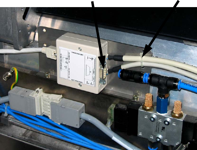
: Connect the second nozzle changer to the one-wire hub.
2
2
: Connect the compressed air hose and reconnect the two nozzle changers to the compressed
air supply using a Y-piece.
2
2
Nozzle changer
connecting cable
Slot for the
reject bin sensor
Assembly instructions Nozzle changer SIPLACE X-Series / D3
11/2011 Edition
53
2.7 Nozzle changer, C&P 6/12 placement head
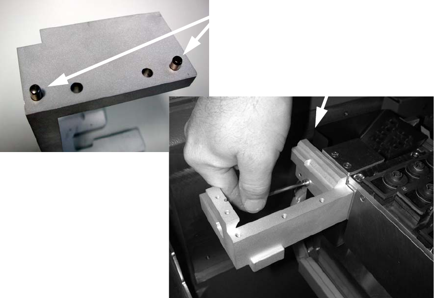
: Switch the placement system off at the main switch.
: Tap the pins into the appropriate holes in the nozzle ejector mount.
2
2
2
2
2
2
2
2
2
2
2
2
Pins
DIN 6325 - 5m5 x 16-St, item no.: 00619866-xx
Screws
DIN912-M5 x 16-8.8, item no.: 00845044-xx
Assembly instructions Nozzle changer SIPLACE X-Series / D3
11/2011 Edition
54
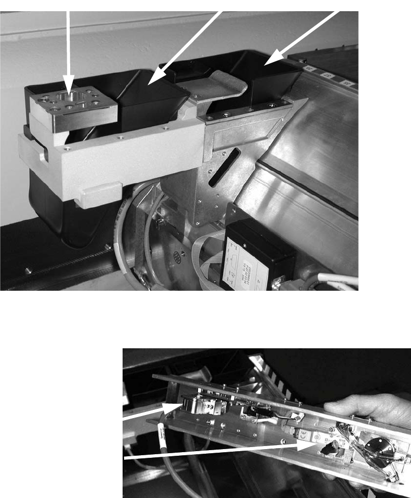
: Fit the nozzle take-off device
(screws: DIN 7991-M4 x 20-8.8 (item no.: 00333782-xx).
: If there is one, fit the reject bin sensor from the component reject park position on the nozzle
ejector mount (see the retrofit instructions for the reject bin sensor SIPLACE X series (item no.:
00194550-xx).
: Insert the reject bin.
2
: Plug the cable and the compressed air hose into the C&P head nozzle changer.
The cable for row 1 is marked "a".
2
Reject bin
Reject bin, second row
Nozzle take-off device
Cable
Compressed
air connector