00194482-02_AI_NozzleChanger_X_605_DE+EN.pdf - 第64页
Assembly instructions Nozzle changer SIPLACE X-Series / D3 11/2011 Edition 64 2.9 Commissioning the nozzle changer : When you fill a magazine with a certain nozzle type for the first time, atta ch an adhesive label to id…

Assembly instructions Nozzle changer SIPLACE X-Series / D3
11/2011 Edition
63
SITEST 2
: Start SITEST (Service engineer mode).
: Carry out a full reference run.
: Switch to the "C&P head" menu.
: If necessary, switch to the "Nozzle changer configuration" menu and fill the magazines with
nozzles.
: Switch to the "Nozzle changer magazine functions" menu.
2
2
: Calibrate the magazine positions, pick-up positions and pick up heights one after the other.
2
2
2
2
2
2

Assembly instructions Nozzle changer SIPLACE X-Series / D3
11/2011 Edition
64
2.9 Commissioning the nozzle changer
: When you fill a magazine with a certain nozzle type for the first time, attach an adhesive label
to identify the type.
2
: Fill the magazines off the placement machine.
: Only ever replace complete magazines.
: Open the locking plate and place the nozzles in the nozzle holders.
: Close the locking plate so that the nozzles cannot drop out of the magazines.
2
2
Before you fill magazines, make sure that all the nozzles on the Collect&Place head have been
returned to their magazines. 2
2
2
Do not allow components to drop onto the magazines. If they do, they could jam the locking plate.
Clean the magazines and free locations regularly with a vacuum cleaner (see Preventive Mainte-
nance). 2
2
2
2
2
2
2
2
2
2
2
2
2
2
2
2
Assembly instructions Nozzle changer SIPLACE X-Series / D3
11/2011 Edition
65
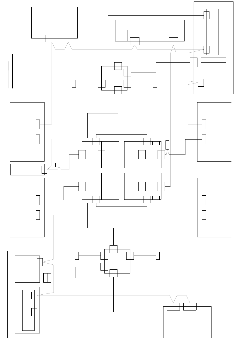
2.10 Circuit diagrams / pneumatic diagrams
2
Fig. 2.10 - 1 Circuit diagram X4 (the wiring of the one-wire hub is the same for all X machines)
X125X126
CAN INCAN OUT
X115X116
CAN INCAN OUT
CAN
PCB control
X22ao
X22ao
CAN I/O module 00355 051 (qb)
So
PinSoPin
So
So
0301 0050
0301 0051
X2rd
X145
CAN IN
So
So
Vision control
00363961 (qd)
CAN
Main distributor 0301 0004 (qa)
X2qd
X2qd
CAN
X2qf
Dock.unit 2 Dock.unit 1
Axis unit 2/3
0301 6110
X30_2sq
CAN
Dock.unit 3
X136
CAN OUT
Pin
X2rd
CAN
CAN
Sub-distributor 0301 0005 (ra)
Vision control
00363961 (rd)
Dock.unit 4
0301 0054
Computer unit
X135
CAN IN
So
So
X68
Ambient pressure sensor
Pneumatic unit
Placement area 2
Placement area 1
CAN bus wire assignment
Wire no. assignment, Sub-D PIN
1
2
3
4
5
6
7
8
9
CAN
X30_2sq
X30_1sq
So
X30_1sq
So
X30_2tq
So
X30_1tq
X146
CAN OUT
Pin
1-wire CAT5 interface
0304 1578 (qf)
X2qf
X2rf
CAN I/O module 00355 051 (rb)
So
0304 1578
1-wire CAT5 interface (rf)
X2rf
Axis unit 1/4
0301 6110
CAN
0301 6643
X7pn X6pn
X7pn
So
CAN card
X6pn
CAN bus 1CAN bus 2
So
X30_2tq X30_1tq
CAN
0301 0052
0301 0059
Distributor
0304 0219 (qk)
X5qk
X5qk
X3qk
X3qk
X6qf
X6qf
0304 1626
Patch cable 3 m
X5rk
X5rk
Distributor
0304 0219
0304 1626
Patch cable 3 m
X6rf
X6rf
0301 0053
X1hq
X4qk
X2qk
X2qk
To 1-wire hub CAT5
X1gq
X4qk
To 1-wire hub CAT5
0304 1627
Patch cable 3 m
0304 1628
Patch cable 3 m
X1qk
X1qk
0300 9826
X2rk
X1fq
X4rk
X1kq
X2rk
To 1-wire hub CAT5
To 1-wire hub CAT5
0304 1627
Patch cable 3 m
0304 1628
Patch cable 3 m
X15qa
X15qa
X15ra
X15ra
X1rk
X1rk
0300 9839
X3rk
X3rk
X4rk
GND
CAN_INT
PowerFail
Spare
RESET
"1-Wire"
CAN_H
CAN_L
GND
3
9
5
8
4
2
7
6
1
1-wire CAT5
1-wire CAT5
(rk)
CAN In
CAN In
So
Switch pos.: bottom
0304 2214 (ge)
1-wire CAT5 gantry
Cable carrier interface
Switch pos.: top
0304 2214 (he)
1-wire CAT5 gantry
So
Cable carrier interface
Patch cable 3 m
0304 1629
G3
X1ge
X1he
X40ca
X5he
X2he
X2he
X40ca
X4he
CAN
0304 2347
0301 0622
0301 0612
1-wire bridge
P2
X2ge
X2ge
X40ba
CAN
X4ge
X1ge
X40ba
X5ge
G4
X5ke
1-wire CAT5 gantry
X40da
X4ke
X40da
Switch pos.: top
0304 2214 (ke)
CAN
So
CAN In
Spare
X30_1sq
X1ke
X2ke
X2ke
0304 2214 (fe)
X4fe
Switch pos.: bottom
Cable carrier interface
Cable carrier interface
X40aa
CAN
(ca)
(ba)
0301 0622
0301 0612
P1
(da)
(aa)
1-wire bridge
0304 2347
X2fe
X2fe
X5fe
1-wire CAT5 gantry
X40aa
CAN In
So
X1fe
X1fe
Patch cable 3 m
0304 1629