X4电路图.pdf - 第237页
4 - ii SIPLA CE X-Se ries De tai led Ci rcuit D iagra ms Fold er 08/2006 US Editi on
SIPLACE X-Series Detailed Circuit Diagrams Folder
08/2006 US Edition
4 - i
4 Assemblies - overview diagrams
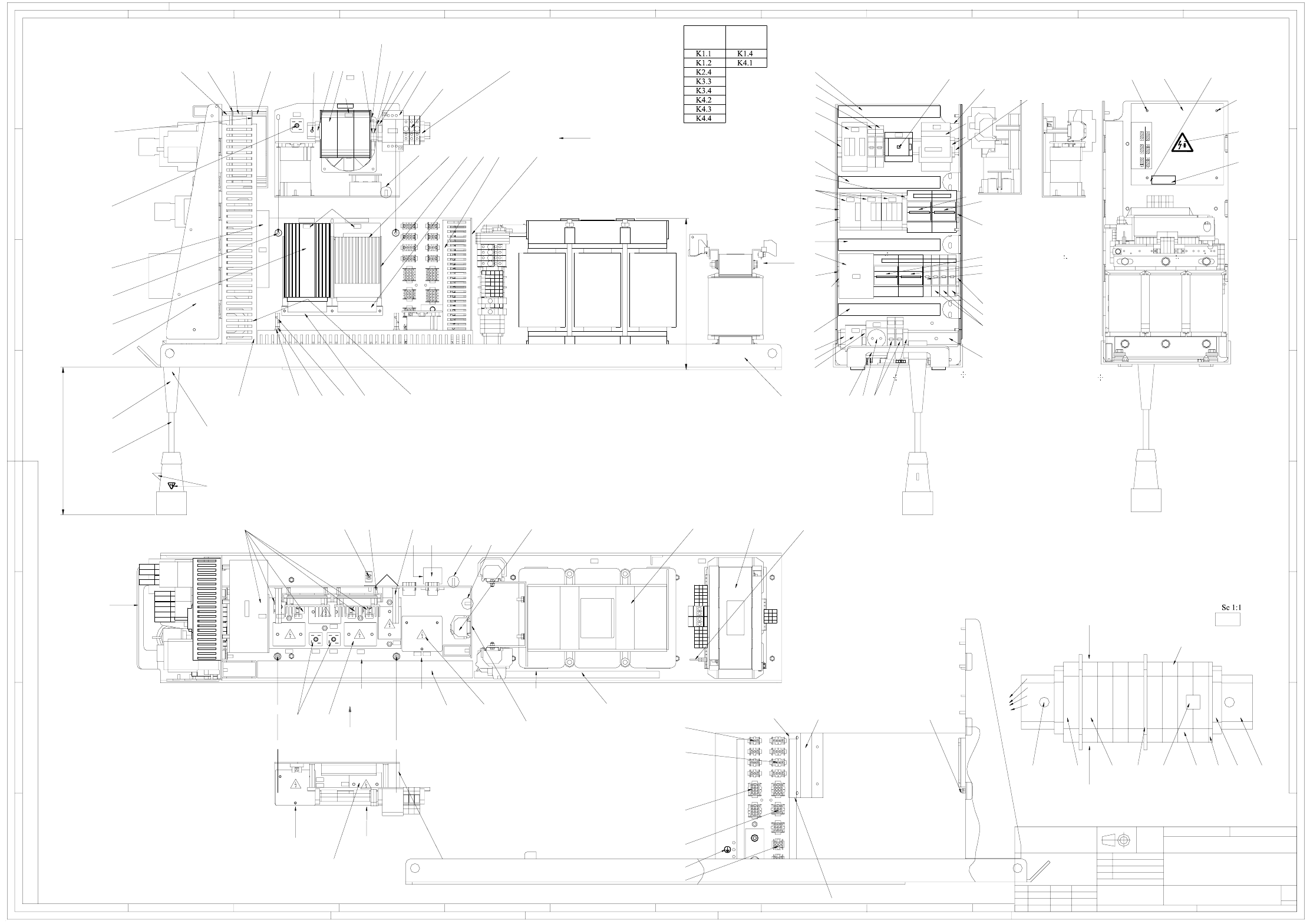
00354626-120101TD1 Power supply unit, SIPLACE X-Series (sh. 1 of 2) 4 - 1
00354626-120101TD1 Power supply unit, SIPLACE X-Series (sh. 2 of 2) 4 - 2
03013143-010201MD4 Module/sensors, head plate assy 4 - 3
03039079-010101TD3 A364 axis unit, wiring (sh. 1 of 2) 4 - 4
03039079-010101TD3 A364 axis unit, wiring (sh. 2 of 2) 4 - 5
03042047-010101TD3 A364 axis unit, front view (sh. 1 of 3) 4 - 6
03042047-010101TD3 A364 axis unit, rear view (sh. 2 of 3) 4 - 7
03042047-010101TD3 A364 axis unit (sh. 3 of 3) 4 - 8
03046225-010101TD1 Main distributor, SIPLACE X-Series 4 - 9
03046226-010101TD1 Sub-distributor, SIPLACE X-Series 4 - 10
03048002-010101GD4 Label, A364 axis unit, 2-gantry machine (sh. 1 of 2) 4 - 11
03048002-010101GD4 Label, A364 axis unit, 2-gantry machine (sh. 2 of 2) 4 - 12
03048003-010101GD4 Label, A364 axis unit, 3-gantry machine (sh. 1 of 3) 4 - 13
03048003-010101GD4 Label, A364 axis unit, 3-gantry machine (sh. 2 of 3) 4 - 14
03048003-010101GD4 Label, A364 axis unit, 3-gantry machine (sh. 3 of 3) 4 - 15
03048004-010101GD4 Label, A364 axis unit, 4-gantry machine (sh. 1 of 3) 4 - 16
03048004-010101GD4 Label, A364 axis unit, 4-gantry machine (sh. 2 of 3) 4 - 17
03048004-010101GD4 Label, A364 axis unit, 4-gantry machine (sh. 3 of 3) 4 - 18
03048274-010101TD3 Computer unit 4 - 19
03048275-010101GD4 Machine label, computer unit 4 - 20
4 - ii
SIPLACE X-Series Detailed Circuit Diagrams Folder
08/2006 US Edition
4 - 1
4 Assemblies - overview diagrams
00354626-120101TD1 Power supply unit, SIPLACE X-Series (sh. 1 of 2)
Warning
E1
X98
E1
X10
X12
X16
X17
X18
X15
X14
X5
X4
X3
X2
X13
X8
X9
X6
X7
DC-DC 24V DC-DC 5V/24V
U2
U20
K1
X102
R1
U10
U1
K6
T1
K5
K4
K3
K2
EST ESS
C1
Z1
F1
F11 F5
U30
V51
Q1
U4 U5
Q2
U6
U7
X100
U8
T2
U9
F2 F10 F6 F8 F12 F13
F4 F7
U3
F14
U11
C2
R3
U60
U70
Power Fail
Plug p osition f or differe nt input voltages
X3 X3
230
Input voltage
X2
400
X1
X2
X1
Technical aspects
ModifiedStat.
BRW1TZAV109-01
SIEMENS
Repl. f.
Date Name
A&D
Author
Check.
Stand.
Date
Type 4AV1302-1CT00-1M
Untol.
Scale:
Replaced by
AutoCAD
Weight:
Sheet
A
B
C
D
E
F
G
H
12
3
456789
12
3
4
5678910
11 12
A
B
C
D
E
F
G
CONFIADO COMO SECRETO INDUSTRIAL
RESERVADOS TODOS LOS DERECHOS
PROPRIETARY DATA
ALL RIGHTS RESERVED
ALLE RECHTE VORBEHALTEN
ALS BETRIEBSGEHEIMNIS ANVERTRAUT
Projecting end of the sheathing - screwed cable on the side of terminal block X100: 15+5.
(61, 102 only here)
Above fan
Fan unit line exit position. Red wire on X98-1.2, blue wire on X98-3.2.
Fix lines using cable ties.
Fan unit direction of air flow
Note corresponding casing designation
172 173172
3030
31
44
169 (Note the correct position (as shown) to the locking device)
t = 30s
H
H
Pos. 168 (attached to the U tray in front of the socket)
L3
L3
L2
L1
PE4
PE3
PE2
PE1
N
166
171 8.)
30
165, 167, 170
Sequence:
F21, F22, F23
91, 90, 102, 115, 164
162
K
t = 30s
75
on base plate
93
83 (fixed with glue)
101, 114, 156
Separate label strips here
Fit
151
152
135
115
127, 134, 129
127, 134
127, 134
154, 108, 155
G
150, 105, 110, 123
123
153
57, 104, 109,
114 1.) 3.)
55 3.)
E
A
U
1
1
(
h
i
d
d
e
n
)
49
Type label as per TBV,
Inspector's stamp (attached on the U tray, legible in the direction of the arrow)
Use cable ties to fix the transformer T2 lines here to the terminal support
K4.5
Labels fitted on the right-hand side.
G
65
74
66
67
68
64
D
A
E
B F
T1- primary transf. lines fixed with pos. 125 here.
F
C
Terminal block X100, see detail
PE line, cable harness, pos. 31
PE line, pos. 513 from pos. 72 (cable harness).
Form line to a roll (dia. approx. 200).
141 Printed as shown
90, 110, 115
50 4847 4546 29 10
Terminal block X100
79
78
82, 100, 130
103, 108, 124
103, 108, 124
(2x each)
103, 132
69 (PCB1)
100, 131
(PCB2)
15
16
14
19
92
20
21
18
17
17
30
9, 91, 90, 102, 115
29 (When lacking space: use type 280 Wago term.)
29
29
29
22
11, 91, 90, 102, 115
30
22
23
25
24
30
26
13
32, 105,
110, 115
3938
41, 90, 61
31
62, 8, 63 4.)
7, 100, 113
40, 103, 81
42, 90, 61
42, 90, 61
41, 90, 61
41, 90, 61
41, 90, 61
41, 90, 61
56, 104, 109, 114 3.)
57, 104, 109, 114 1.) 3.)
55 3.)
4, 101,
114, 128
3
30
9, 91, 90, 102, 115
9, 91, 90,102,
115 (2x),
61 (1x, position s. F)
Terminal block X20, see detail
2 6.) 7.)
1 5.) 7.)
84
83 all four cut-outs
12 Switch shaft shortened to 58 mm, fitted in the center of the top hat rail
2.)
(NO)
(NC)
105
102
115
110
K1.4
K4.4
K4.1
K1.1
K1.2
K4.3
K3.4
K4.2
K3.3
K2.4
max. 328
(5050)
±50
Cramer
Cramer
Cramer
26.05.05
25.01.05
12.07.05T9804
T8949
T96821P
1N
1Q
Document no.:
00354626-110401TD1
ISO 2768 - mH
1/2
Power supply unit
19.03.2002
Cramer
Linneck
Westermann
DM
without a cover, Pos. 43
M/
69
103, 131
90, 110,
Fit
M/
Pos. 27 Pos. 28
Document no.:
00354626-120101TD1
dimens. to
Copyright reserved