X4电路图.pdf - 第238页
4 - 1 4 As sem bl ies - ov erv iew di agra m s 0035462 6-120 101 TD1 Power su pply unit , SIPLA CE X-Se ries (sh. 1 of 2 ) Warning E1 X98 E1 X10 X12 X16 X17 X18 X15 X14 X5 X4 X3 X2 X13 X8 X9 X6 X7 DC-DC 24V DC -DC 5V/24V…
4 - ii
SIPLACE X-Series Detailed Circuit Diagrams Folder
08/2006 US Edition
4 - 1
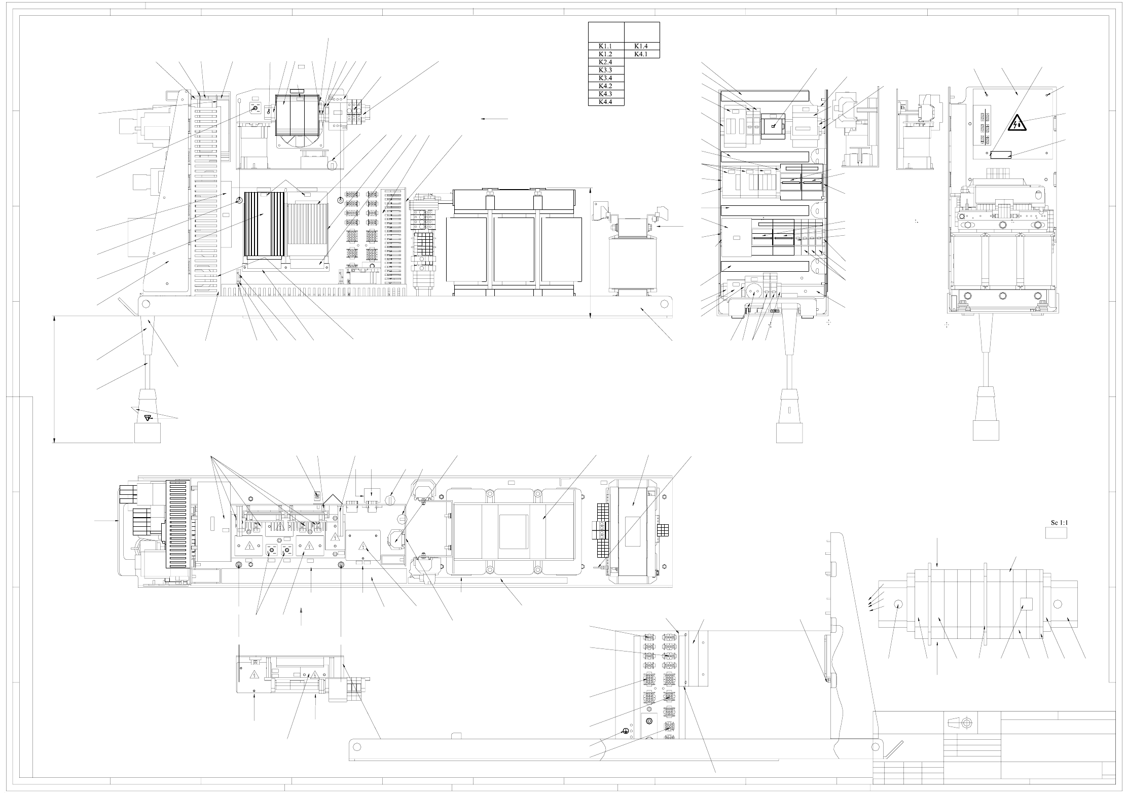
4 Assemblies - overview diagrams
00354626-120101TD1 Power supply unit, SIPLACE X-Series (sh. 1 of 2)
Warning
E1
X98
E1
X10
X12
X16
X17
X18
X15
X14
X5
X4
X3
X2
X13
X8
X9
X6
X7
DC-DC 24V DC-DC 5V/24V
U2
U20
K1
X102
R1
U10
U1
K6
T1
K5
K4
K3
K2
EST ESS
C1
Z1
F1
F11 F5
U30
V51
Q1
U4 U5
Q2
U6
U7
X100
U8
T2
U9
F2 F10 F6 F8 F12 F13
F4 F7
U3
F14
U11
C2
R3
U60
U70
Power Fail
Plug p osition f or differe nt input voltages
X3 X3
230
Input voltage
X2
400
X1
X2
X1
Technical aspects
ModifiedStat.
BRW1TZAV109-01
SIEMENS
Repl. f.
Date Name
A&D
Author
Check.
Stand.
Date
Type 4AV1302-1CT00-1M
Untol.
Scale:
Replaced by
AutoCAD
Weight:
Sheet
A
B
C
D
E
F
G
H
12
3
456789
12
3
4
5678910
11 12
A
B
C
D
E
F
G
CONFIADO COMO SECRETO INDUSTRIAL
RESERVADOS TODOS LOS DERECHOS
PROPRIETARY DATA
ALL RIGHTS RESERVED
ALLE RECHTE VORBEHALTEN
ALS BETRIEBSGEHEIMNIS ANVERTRAUT
Projecting end of the sheathing - screwed cable on the side of terminal block X100: 15+5.
(61, 102 only here)
Above fan
Fan unit line exit position. Red wire on X98-1.2, blue wire on X98-3.2.
Fix lines using cable ties.
Fan unit direction of air flow
Note corresponding casing designation
172 173172
3030
31
44
169 (Note the correct position (as shown) to the locking device)
t = 30s
H
H
Pos. 168 (attached to the U tray in front of the socket)
L3
L3
L2
L1
PE4
PE3
PE2
PE1
N
166
171 8.)
30
165, 167, 170
Sequence:
F21, F22, F23
91, 90, 102, 115, 164
162
K
t = 30s
75
on base plate
93
83 (fixed with glue)
101, 114, 156
Separate label strips here
Fit
151
152
135
115
127, 134, 129
127, 134
127, 134
154, 108, 155
G
150, 105, 110, 123
123
153
57, 104, 109,
114 1.) 3.)
55 3.)
E
A
U
1
1
(
h
i
d
d
e
n
)
49
Type label as per TBV,
Inspector's stamp (attached on the U tray, legible in the direction of the arrow)
Use cable ties to fix the transformer T2 lines here to the terminal support
K4.5
Labels fitted on the right-hand side.
G
65
74
66
67
68
64
D
A
E
B F
T1- primary transf. lines fixed with pos. 125 here.
F
C
Terminal block X100, see detail
PE line, cable harness, pos. 31
PE line, pos. 513 from pos. 72 (cable harness).
Form line to a roll (dia. approx. 200).
141 Printed as shown
90, 110, 115
50 4847 4546 29 10
Terminal block X100
79
78
82, 100, 130
103, 108, 124
103, 108, 124
(2x each)
103, 132
69 (PCB1)
100, 131
(PCB2)
15
16
14
19
92
20
21
18
17
17
30
9, 91, 90, 102, 115
29 (When lacking space: use type 280 Wago term.)
29
29
29
22
11, 91, 90, 102, 115
30
22
23
25
24
30
26
13
32, 105,
110, 115
3938
41, 90, 61
31
62, 8, 63 4.)
7, 100, 113
40, 103, 81
42, 90, 61
42, 90, 61
41, 90, 61
41, 90, 61
41, 90, 61
41, 90, 61
56, 104, 109, 114 3.)
57, 104, 109, 114 1.) 3.)
55 3.)
4, 101,
114, 128
3
30
9, 91, 90, 102, 115
9, 91, 90,102,
115 (2x),
61 (1x, position s. F)
Terminal block X20, see detail
2 6.) 7.)
1 5.) 7.)
84
83 all four cut-outs
12 Switch shaft shortened to 58 mm, fitted in the center of the top hat rail
2.)
(NO)
(NC)
105
102
115
110
K1.4
K4.4
K4.1
K1.1
K1.2
K4.3
K3.4
K4.2
K3.3
K2.4
max. 328
(5050)
±50
Cramer
Cramer
Cramer
26.05.05
25.01.05
12.07.05T9804
T8949
T96821P
1N
1Q
Document no.:
00354626-110401TD1
ISO 2768 - mH
1/2
Power supply unit
19.03.2002
Cramer
Linneck
Westermann
DM
without a cover, Pos. 43
M/
69
103, 131
90, 110,
Fit
M/
Pos. 27 Pos. 28
Document no.:
00354626-120101TD1
dimens. to
Copyright reserved
4 - 2
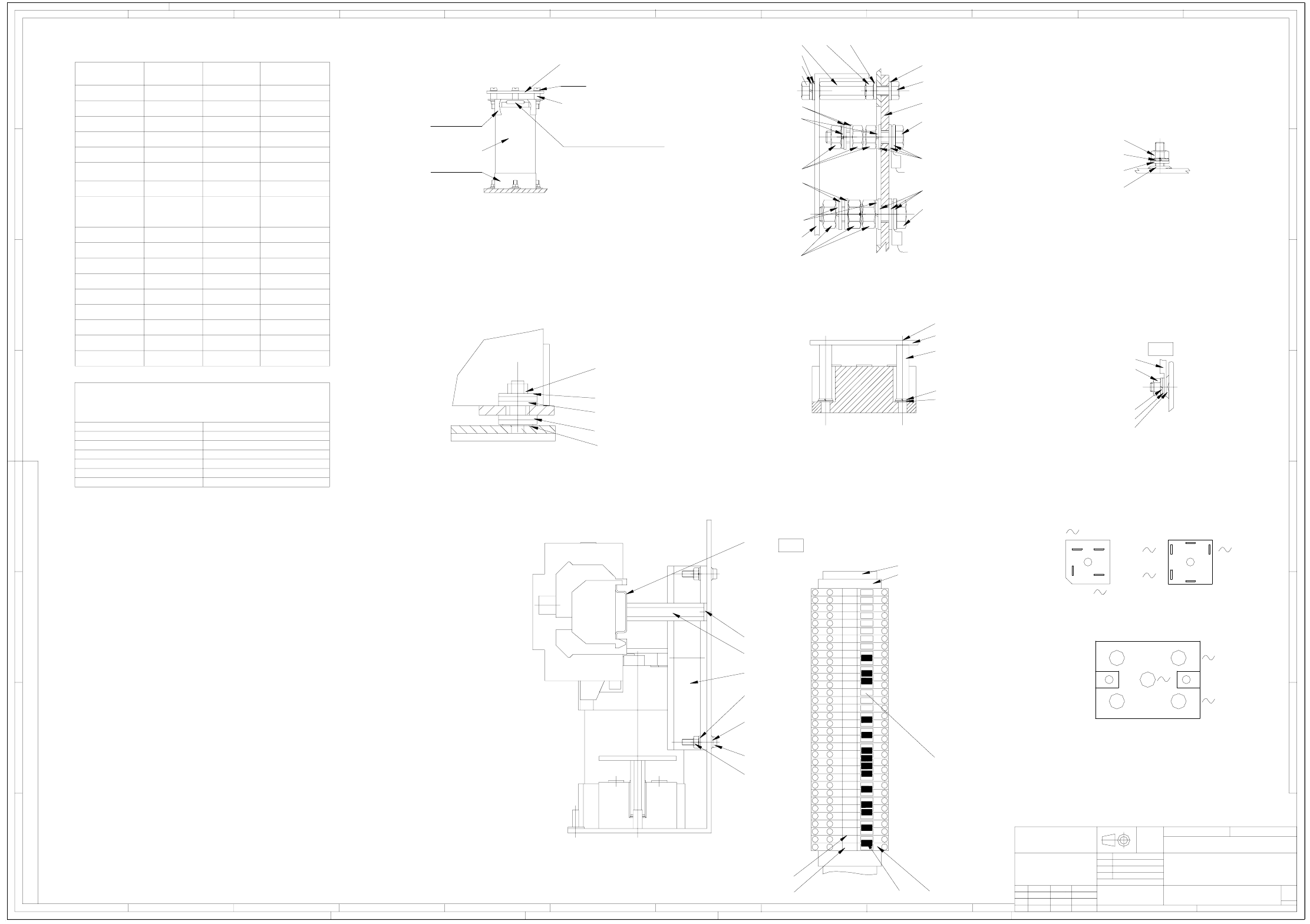
00354626-120101TD1 Power supply unit, SIPLACE X-Series (sh. 2 of 2)
1
44 4
7
4
4
1
330
Power supply unit
Type 4AV1302-1CT00-1M
BRW1TZAV109-01
Replaced by
AutoCAD
2/2
Sheet
Repl. f.
DM
Westermann
Linneck
Cramer
19.03.2002
Date
Author
Check.
Stand.
Document no.:
00354626-110401TD1
DateModifiedStat. Name
12.07.05
25.01.05
26.05.05
T8949
T9804
1N
1Q
T96821P
Cramer
Cramer
Cramer
Sc 1:1
(RGP 1-20, Numbering sequence from bottom to top)
Sc 1:1
(Rectifier section)
Sc 1:1
Sc 1:1
2x annular cable lug
2x annular cable lug
X12 M8
X11 M10
Rectifier connections defined in the drawing
Sc 1:1
Sc 1:1
Sc 1:1
Sc 1:1
Transformer attachment
M/
K2, K3, K4
1.)
2.)
4.)
3.)
K6
K1
K5
Q2
Q1
Run line through handle, fit cable gland and bracket; do not fit the bracket on the base.
Fixing bolt for bracket (pos. 8) with pos. 100 and 113 (do not tighten).
Prevent touching the negative poles of U3, U6, and U60 by covering them with pos. 86 and pos. 87.
Fit pos. 55, 56, and 57 with heat-conductive paste.
Do not fit the rotary drive, put in a polyethylene bag (Pos.76) and keep with device .
Fit insulating tube over the fixing bolts at X1-11 connector.
Min. distance between lines and transformers 10mm.
Combine transformer lines with pos. 70 up to cable duct.
Combine transformer lines with pos. 71 up to cable duct.
6.)
8.)
7.)
5.)
The blades for the retainers (pos. 29 and 30) must point to the center of the top hat rail.
Fit all contact washers with the teeth pointing to the EPS surface.
Cut pos. 40, 41, and 42 to length as per drawing BRW1TZAV109-01.
Fit pos. 73 as shown. In contrast to the illustration, fit the Fx fuse designations top side.
Unspecified torques as per TNK 116-03 and -09.
Hand-screw plastic connections and observe the low sturdiness.
Wiring as per TG6999140-02 (pos. 72, not illustrated). The other cable harness assemblies and lines as per TBV.
Switch as per TNK 116-09. The cables must not protrude over the basic module external dimensions.
Cut pos. 83 and 84 to length as per drawing BRW1TZAV109-01.
Fit transformers centrally.
Packaging pos. 77 not shown. Packaging as per TT62034-02.
Fit unfolded machine label (pos. 160) to jack ring of T1 with pos 161 over T1.
Cable duct fittings: use disk pos. 119 between base and cable duct for embossed locations.
Make sure not to distort the transportation lock against the DC/DC converter.
Fit transportation lock pos. 157 above the DC/DC converters in the base plate slot toghether with pos. 158 and 103.
Attention : Do not pinch the insulating collars of the wire end ferrules during wiring!
Document no.:
00354626-120101TD1
dimens. to
Untol.
SIEMENS
A&D
Copyright reserved
1
4
2
23
3
23
2
2
23
3
3
2
5
2
3
6
3
2
89
3
2
23
3
56
5
2
6
3
2
2
56
3
3
2
3
5
23
6
5
23
6
89
2
89
3
5
5
23
6
6
56
2
56
3
32
Wago line jumper, pos. 174:
Make sure to cut off one connector from the line very short.
(connector no longer used).
Strip back the insulation from the line end 10mm and crimp wire end ferrule onto pos. 176.
- Plug connector in X20-9 socket, wire end ferrule in T1-R13; tighten with 0.8 Nm.
80
59 (2x)
60
89
D
Tighten nut until the upper plastic disks have a convex shape.
59 (T1: 2x, T2: 3x)
102
105
110
G
115
Cable lug
120
105
94
121
106
122
107
B
102115
106
133
105
105
123
116
111
107
117
112
43, 79 (centrally)
C
(3x)
E
54
58, 85
109
104
104, 109, 126
34, 108, 103, 113
33
34, 108, 103, 113
37
A
35
103, 140
36, 88 press-fit and solder up.
Insulate with heat-shrinkable tubing
Aux. line
Torque
Designation
Main line
Torque
-
-
-
-
-
-
-
-
-
-
-
1.0Nm
-
-
-
0.8-1.2Nm
0.8-1.2Nm
0.8-1.2Nm
0.8-1.2Nm
-
-
-
-
-
-
0.8-1.2Nm
0.8-1.2Nm
3Nm
1.7Nm
3-4.5Nm
2-2.5Nm
-
0.8-1.2Nm
1.5-1.8Nm
2.5-3NmFx
-
-
3Nm
2NmC1, C2
U3, U6, U60
Z1
Kx
Terminals 1.5Nm
Ground bolts 3Nm
0.5-0.8Nm
U1, U2, U7, U9, U70
U4, U5, U8, U10, U11
F131, F132, F141, F142
F61, F62, F81, F82
4Nm
hand-screwed
Attachment on the casing
Torque
3-4Nm
2.5Nm
Technical aspects
ISO 2768 - mH
Scale: Weight:
1
3
2
3
4
4
7
30
4
1
211
A
B
C
D
E
F
G
H
12
3
456789
12
3
4
5678910
11 12
A
B
C
D
E
F
G
CONFIADO COMO SECRETO INDUSTRIAL
RESERVADOS TODOS LOS DERECHOS
PROPRIETARY DATA
ALL RIGHTS RESERVED
ALLE RECHTE VORBEHALTEN
ALS BETRIEBSGEHEIMNIS ANVERTRAUT
1
4040
X20
137
115
110
105
102
95
102
175
-
+
2
1
+
-
3
2
1
3
1
2
+
-
F21, F22, F23
Z2
--0.5-0.8NmX102
0.5Nm --
M8 12Nm
M6 8Nm
M5 3.8Nm
M4 1.9Nm
M3 0.8Nm
Torque
0.4Nm
Thread size
M2.5
Torques for nuts, screwed onto mold-in threaded bolts,
unless otherwise noted. (TNK does not apply.)
103
118
100
140
K
30
9, 90, 110, 115
Terminal block X20
52 One each between the potentials
141 Printed as shown
51
53
1
1
171819
1
1
1
1
15
1
1
13
12 14
4
16
1
11
10
1
1
91010
4
7
1
67
1
1
655
4
4
8
1
11
RGP